
Fin efficiency explained by BQUQ: when tall thin fins stall, the m·L rule, and real limits for extruded aluminum heat sinks from a Dongguan factory.
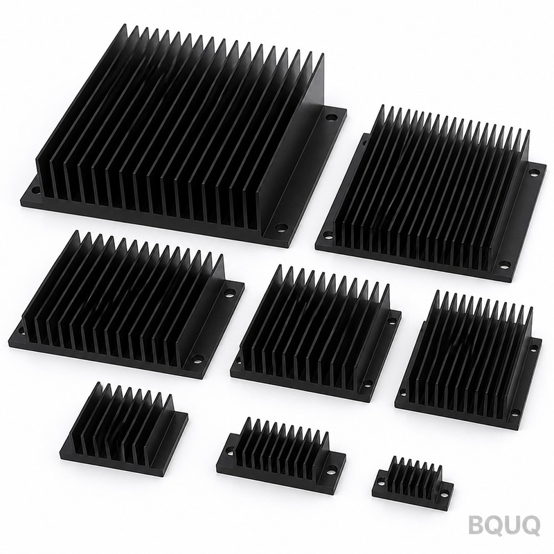
Fin Efficiency: Why Tall Thin Fins Stall
Short answer: a fin stops earning its keep when its efficiency falls below roughly 60–70%, and that happens when the fin gets taller and thinner than the material can feed heat down its length. At a convection coefficient of 25 W/m²·K, a 1.0 mm aluminum fin at 40 mm height still runs about 89% efficient; stretch the same fin to 80 mm and it drops to about 67%. Double the height again and almost all added surface stops working. The practical takeaway: beyond a fin height of roughly 50–70 mm on extruded aluminum, you are paying for metal that conducts little heat.
Fin efficiency is the quiet killer of heat sink performance. Most buyers size a heat sink by counting surface area, and most are wrong, because a square centimeter of metal at the fin tip does not reject the same heat as a square centimeter at the base. The heat must travel by conduction up the fin, and every millimeter of that trip happens through a shrinking temperature difference. That is why two heat sinks with identical total surface area can differ in real-world performance by 30% or more.
Why "More Surface Area" Stops Being True
The heat leaving a fin tip is limited by how much temperature difference is left at that point. Define fin efficiency as actual heat rejected divided by the heat the fin would reject if the entire fin sat at base temperature. A 100% efficient fin is a theoretical fin made of a perfect conductor; real fins run between roughly 40% and 95%.
Conduction resistance is what breaks the promise of tall fins. Aluminum 6063 conducts about 200 W/m·K and copper about 390 W/m·K, which sounds like plenty, until you realize the heat is travelling along the length of a fin that is only 1–2 mm thick. A 100 mm tall, 1 mm thick fin has a length-to-thickness ratio of 100:1, and at that ratio even copper stops being a "perfect conductor." This is covered in more depth in our fin design guidelines, but the core physics is simple: thin geometry plus long conduction path equals a warm fin tip that does almost nothing.
Efficiency also explains why weight is a poor proxy for performance. A compact sink with short, thick fins can beat a taller finned rival on a concentrated source, and a thin skived field can beat both under a strong ducted fan. Compare sinks by measured or calculated resistance at your airflow, never by kilogram or by square centimeter alone.
The m·L Number That Predicts Stall
Thermal engineers collapse fin geometry into a single dimensionless number. For a rectangular plate fin, the fin parameter is m = √(2h/kt), where h is the convection coefficient in W/m²·K, k is fin conductivity, and t is fin thickness in meters. Multiply m by fin height L and you get m·L, the number that controls efficiency:
η = tanh(m·L) / (m·L)
When m·L is below 0.5 the fin is nearly perfect at 95%+. When m·L passes 1, efficiency slides below 80%. By m·L = 2 you are below 50%, and every additional millimeter of height adds almost nothing. The table below applies that formula to a 6063-type aluminum fin at h = 25 W/m²·K:
| Fin thickness | 20 mm height | 40 mm height | 60 mm height | 80 mm height |
|---|---|---|---|---|
| 0.5 mm | 94% | 80% | 65% | 53% |
| 1.0 mm | 97% | 89% | 78% | 67% |
| 2.0 mm | 98% | 94% | 87% | 80% |
Read the columns, not just the rows. A 2.0 mm fin at 80 mm height (80%) beats a 0.5 mm fin at 40 mm height (80%) for the same height-to-surface trade, and the thicker fin is also stronger and easier to extrude. Thin fins only make sense when the fin is short, the airflow is gentle, or the material is copper.
Where Tall Thin Fins Stall in the Real World
Real heat sinks stall earlier than the fin-efficiency formula suggests, for three reasons. First, natural-convection boundary layers merge in narrow channels: below roughly 5–6 mm of fin spacing, adjacent fins choke each other's airflow and the effective convection coefficient drops so far that adding rows of tall fins buys almost nothing. For natural convection, optimum spacing on 50–100 mm tall fins typically lands between 8 and 14 mm.
Second, manufacturing reality. An extruded 6063 profile with 60 mm fins needs roughly 1.3–2.0 mm fin thickness to fill the die properly, and fin height above about 80 mm starts fighting die deflection and profile straightness. Skived and bonded-fin sinks can run thinner and taller, but then you pay assembly cost per fin. Third, structural reality: tall thin fins vibrate in fan airflow, bend in handling, and break in shipping, which is why many 1U-style designs cap fin height well below what the math allows.
Design Rules That Actually Work
| Design goal | Rule of thumb | Notes |
|---|---|---|
| Natural convection | Fin spacing 8–14 mm, height 25–50 mm | Taller fins need wider gaps to breathe |
| Forced convection, ducted | Spacing 3–6 mm, height 20–60 mm | Fan static pressure decides how narrow you can go |
| Extruded aluminum | Fin thickness ≥1.3 mm, height ≤80 mm | Below 1.0 mm thickness, extrusion gets marginal |
| Thin tall fins (0.4–0.8 mm) | Use skived or bonded construction | Cost per fin rises; only wins when area density is the goal |
| Height beyond ~80 mm | Add a heat pipe or vapor chamber layer instead | Spreads heat laterally before it climbs the fins |
The pattern behind the table: spend your surface-area budget where fins are short enough to stay above ~70% efficiency, or move the heat laterally first with a heat pipe or vapor chamber so the fins you do use all operate near the base temperature. A 20 mm tall fin set on a vapor chamber usually beats a 60 mm fin set bolted straight to a hot spot, at a fraction of the weight.
When You Still Need Real Height
Tall fins are not wrong; they are wrong when chosen thoughtlessly. Applications with a large, uniform heat source and strong ducted airflow, such as IGBT heatsinks in drives or high-power LED modules, genuinely use 50–80 mm fins efficiently because the whole base is hot and the fan forces air through the full channel. The mistake is a small concentrated source, like a single 25 W chip, under a tall narrow fin field: most of the fins sit far from the heat source and conduct almost nothing. That geometry is exactly where heat sink sizing calculations go wrong when they assume uniform base temperature.
What Changes When You Buy, Not Just Design
The fin efficiency analysis changes procurement as much as design. For volume production, extrusion is normally the cheapest way to make a finned sink, but the die is a fixed cost: a simple 6063 profile die typically runs in the range of $800–$2,500 depending on length, complexity and the toolmaker, and it only pays off once the profile quantity justifies it. Below that volume, machining a sink from solid bar or plate, or skiving fins from a billet, avoids the die entirely and lets you change geometry on every order, which is why prototype and mid-volume runs almost always start machined rather than extruded.
When you compare supplier quotes, ask the three questions that a raw area count hides. What fin efficiency did the quotation assume at your airflow? An extruded profile at 60% efficiency and one at 85% are different products with identical square centimeters. What base thickness is specified, and does it spread heat from your real source size? And what is the construction, extruded monolith, bonded fin or skived, because that decides the fin thickness and pitch the process can honestly hold? A supplier who answers with airflow and efficiency numbers is doing thermal engineering; one who answers only with weight and area is selling metal.
Manufacturing reality sits behind the math too. Fins specified thinner than the process can hold show up as waviness, die marks or vibration in service, not in the quotation. At BQUQ we machine heat sink bases and mounting features to ±0.005 mm, finish extruded profiles with CNC-machined faces, and black-anodize where radiation helps the passive case, all under one roof in Dongguan. Send the fin geometry, heat source size and airflow with the drawing to sc@bquq.com or WhatsApp +86 13713157787, and the 12-hour quote comes back with a construction recommendation, not just a price.
Frequently Asked Questions
Q: What is fin efficiency in a heat sink?
A: Fin efficiency is the ratio of heat a real fin rejects to the heat it would reject if the whole fin were at base temperature. Real fins run roughly 40–95%; tall thin fins sit at the low end because conduction resistance leaves the fin tip nearly at air temperature.
Q: What fin height is too tall for an extruded aluminum heat sink?
A: In practice, above roughly 60–80 mm on a 1.0–2.0 mm extruded fin the added height returns less than 15–20% of the extra surface you paid for, and extrusion tooling limits height to about 80 mm before profile quality suffers. If you genuinely need more height, consider bonded or skived fins or a heat pipe base.
Q: Why does my heat sink get hotter when I add taller fins?
A: It should not get hotter, but it often stops getting cooler: beyond m·L ≈ 1–2, fin efficiency collapses and extra height adds negligible heat rejection while blocking airflow to the fins behind it, especially in natural convection. Measure base temperature rise, not total surface area.
Q: How do I know if my fins are efficient without testing?
A: Compute m·L = L·√(2h/kt) using your worst-case convection coefficient and check fin efficiency with η = tanh(m·L)/(m·L). If efficiency is below roughly 70%, shorten the fins, thicken them, use copper, or spread heat laterally with a heat pipe or vapor chamber.
Q: Can BQUQ help if my design really needs tall thin fins?
A: Yes. We machine, extrude-combine, skive and stamp heat sink components in our Dongguan plant and will tell you honestly when a fin geometry wastes metal. Send your drawing, power level and airflow to sc@bquq.com and we will quote within 12 working hours.
Related Resources
- Heat Sink Fin Design Guidelines — spacing, height and thickness trade-offs behind every fin field.
- CNC-machined heat sinks — precision-machined sink bodies and mounting features when extrusion limits bite.
- About BQUQ — an ISO9001-certified source factory in Dongguan running CNC, stamping, spring and heat sink lines under one roof.
- Contact us — send your drawing for a quote within 12 working hours.
Authored by the BQUQ Engineering Team. BQUQ is an ISO9001-certified source factory in Dongguan, China, running CNC machining, metal stamping, custom springs, heat sink and collet lines under one roof. Send drawings to sc@bquq.com or WhatsApp +86 13713157787 for a quote within 12 working hours. www.bquq.com


