
BQUQ shows how to calculate heat sink surface area from watts, convection and temperature rise, with worked examples and extrusion packing numbers.
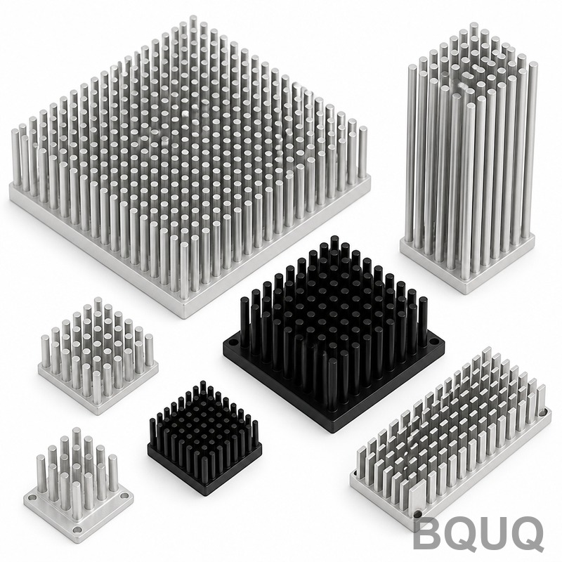
Heat Sink Surface Area: The Number Behind Every Design
Short answer: required surface area comes from A = P/(h·η·ΔT), where P is heat in watts, h the convection coefficient in W/m²·K, η average fin efficiency, and ΔT the allowed temperature rise of the sink base above air. A 50 W load with a 40 °C rise under natural convection (h ≈ 5 W/m²·K, η ≈ 0.8) needs roughly 3,100 cm² of wetted fin area; with forced air at h ≈ 30 W/m²·K the same job takes about 500–700 cm². Estimate the area first, then count fins — buyers who skip the estimate order sinks that are either 3× too big or silently overheating.
Every heat sink is, at heart, a surface-area machine. The metal conducts heat from the source and the surface hands it to the air, and the amount of surface is the biggest single lever in the design. But "more surface" has a catch: the surface only counts if air can reach it and if the fin attached to it is still conducting. That is why the calculation below always pairs raw area with fin efficiency, and why two sinks with identical surface area can perform completely differently.
The Master Equation and What Each Term Means
The steady-state balance is simple. Heat leaving the sink equals convection from its surfaces: P = h·A·ΔT, where ΔT is the difference between the average surface temperature and the air. Because fins are not perfect conductors, real sinks deliver less than the raw area suggests, so the equation carries fin efficiency: P = h·(A·η)·ΔT, rearranged as A = P/(h·η·ΔT).
Each term is a decision, not a constant. P is your heat load, the real dissipated watts, which for electronics is input power minus work output, rarely equal to nameplate. ΔT is a budget choice: the rise you allow between sink base and ambient, set by the component junction limit minus the internal drops. h is set by your cooling mode, roughly 2–10 W/m²·K for natural convection depending on orientation and size, 10–100 for forced air, far higher for liquids. η is the fin efficiency averaged across the fin field, typically 60–95%. The interplay of h and η is exactly why thermal resistance calculation exists: this area number is the geometric half of that budget.
Worked Example: 50 W in Natural and Forced Convection
Run the arithmetic twice to see what cooling mode does to size. A 50 W source, 40 °C allowed rise, fins at 80% efficiency. Natural convection with h = 5 W/m²·K needs A = 50/(5 × 0.8 × 40) = 0.3125 m², about 3,125 cm² of finned surface — a large, heavy extrusion with the classic widely spaced vertical fins. Forced air at a modest h = 30 W/m²·K needs A = 50/(30 × 0.8 × 40) = 0.052 m², about 520 cm², a much smaller and cheaper sink, plus a fan and its noise.
| Cooling scenario | h used | Required area for 50 W at 40 °C rise | Typical footprint |
|---|---|---|---|
| Natural convection, vertical fins | 5 W/m²·K | ~3,100 cm² | 150 × 150 mm base, tall fins |
| Natural convection, large black sink | 7 W/m²·K | ~2,200 cm² | 120 × 120 mm base plus radiation |
| Forced air, low flow | 15 W/m²·K | ~1,050 cm² | 100 × 100 mm base |
| Forced air, ducted fan | 30 W/m²·K | ~520 cm² | 80 × 80 mm base |
| Forced air, high static pressure | 60 W/m²·K | ~260 cm² | 60 × 60 mm base |
Indicative values; real designs adjust for orientation, radiation, altitude and the shape of the heat source. The lesson of the table is scale: the cooling mode moves the required area by roughly an order of magnitude, which is why deciding fan versus no fan is a design decision and not a detail.
From Area to Fins: Packing the Surface
Raw area becomes a fin field through packing density. A bare flat plate of 100 × 100 mm offers only 200 cm² counting both sides; the same footprint with fins multiplies the wetted surface many times. The multiplier depends on construction: extruded aluminum profiles typically pack 200–500 m² of fin surface per cubic meter of envelope, while skived, bonded or folded-fin constructions reach 500–1,500 m²/m³ because their fins are thinner and closer together.
| Fin construction | Typical fin thickness | Typical pitch | Surface density |
|---|---|---|---|
| Extruded 6063 profile | 1.2–2.0 mm | 5–10 mm | 200–500 m²/m³ |
| Skived aluminum | 0.3–0.8 mm | 1–3 mm | 800–1,500 m²/m³ |
| Bonded / folded fin | 0.2–0.6 mm | 2–5 mm | 600–1,200 m²/m³ |
| Stamped / crimped fin | 0.3–1.0 mm | 3–6 mm | 400–900 m²/m³ |
Higher density is not automatically better. Dense thin fins only pay off with enough static pressure to push air through them; in natural convection they choke, and below roughly 5 mm pitch the boundary layers merge and the added area stops working. That is why natural-convection sinks keep wide pitch and modest height while fan-cooled server and drive sinks run dense. Matching construction to airflow is the step where surface-area math meets manufacturing reality, and it is covered in practical detail in our heat sink sizing calculation guide.
The Base Area and Spreading Trap
Fins solve convection, but the heat must first spread across the base to reach them. A concentrated source under a wide base creates a spreading penalty: the base area near the chip is hot and the outer fins run cool, dragging down average η far below the per-fin number. The engineering check is simple: if your heat source occupies less than roughly 10–20% of the base footprint, the spreading resistance is probably larger than the fin resistance, and adding fins is the wrong fix. Options are a thicker base, a copper base or embedded heat pipes, or a vapor chamber to spread the heat before it reaches the fins.
| Heat source vs base | Dominant resistance | Best fix |
|---|---|---|
| Source covers most of base | Fin convection | More area, better airflow |
| Source covers 20–50% of base | Mixed | Thicker base or spreader |
| Small source, wide base | Spreading | Copper insert, heat pipes, vapor chamber |
This is why two suppliers quoting the same watts and the same footprint can deliver very different real performance. The one that accounts for the source footprint and the fin efficiency gives you a sink that meets the number; the one that just counts square centimeters gives you metal. When you send us a thermal inquiry, we ask for the heat source size, not just the watts, and we machine the base thickness and spreader features to match, holding ±0.005 mm where the thermal face needs it. Production machined heat sinks and extruded profiles both start from the same area estimate, and the estimate is where the design is won or lost.
From the Area Estimate to a Real Quote
The area estimate turns into hardware through construction choice and a profile or a machined part. Once the required surface area is known, divide it by the surface density of the intended construction to get the envelope volume, then trade length, width and fin height against the space envelope and the airflow direction. For an extrusion this means choosing a profile cross-section and a cut length; for a machined sink it means sizing a billet and a fin tool path. Both start from the same number, which is why a supplier who asks for watts and rise before quoting is doing the calculation, and one who quotes by envelope size alone is guessing.
Comparing quotes then becomes comparing assumptions. Ask each supplier for the surface density of the proposed construction, the fin efficiency at your airflow, and the base thickness. Two quotes at the same price can differ by 40% in real performance if one assumes skived-density fins at 90% efficiency and the other assumes a coarse extrusion at 60%. Material also moves the number: 6063-T5 extrusion runs at roughly the same price class as 6061 machined stock, while copper multiplies material cost several times and only pays where the aluminum vs copper trade is real.
Indicative cost shape: an extruded aluminum sink is priced by profile weight plus cutting and finishing, typically a few dollars per kilogram of aluminum plus machining time; a CNC-machined sink is priced by machine hours, so its cost tracks complexity and fin count rather than weight. Skived and bonded constructions sit between, with higher per-part cost justified only by surface density that air can actually reach. Stating the quantity and the allowed envelope lets the factory pick the construction that meets the area number at the lowest cost, which is the entire point of sending a target instead of a preferred process.
At BQUQ we quote the comparison, not just the part: extrusion with CNC-finished faces, fully machined sinks, or bonded construction, priced against your quantity with the same thermal target. Every quote states the assumed airflow and the resulting resistance so the area math is visible. Send the watts, rise, envelope and quantity to sc@bquq.com or WhatsApp +86 13713157787 and the response comes back within 12 working hours.
Frequently Asked Questions
Q: What is the formula for heat sink surface area?
A: The basic estimate is A = P/(h·η·ΔT), where P is heat load in watts, h the convection coefficient in W/m²·K, η average fin efficiency, and ΔT the allowed rise of the sink base above ambient. Refine it with fin geometry and spreading checks before tooling.
Q: How many square centimeters of heat sink do I need per watt?
A: Under natural convection, roughly 40–100 cm² per watt at typical 30–50 °C rises; under forced air, roughly 5–20 cm² per watt depending on airflow. These are indicative planning numbers, not substitutes for the full calculation with your ΔT and fin efficiency.
Q: Why does my heat sink have lots of surface area but still run hot?
A: Almost always one of three causes: the fins are too tall or dense for the airflow so effective area is far below the geometric number, the heat source is small so the base spreads heat poorly, or the air never reaches the fins due to bypass. Check fin efficiency and airflow, not just square centimeters.
Q: What surface area does an extrusion heat sink realistically achieve?
A: A practical extruded 6063 profile packs roughly 200–500 m² of fin surface per cubic meter of envelope. To get more area in the same footprint you need skived, bonded or folded-fin construction, which costs more and needs static pressure to work.
Q: What information do you need to size my heat sink?
A: Heat load in watts, the heat source footprint, allowed temperature rise or target case temperature, ambient, and whether airflow is allowed. Send those to sc@bquq.com or WhatsApp +86 13713157787 and BQUQ will respond with a machining and manufacturing recommendation within 12 working hours.
Related Resources
- Heat Sink Thermal Resistance Calculation — the full Rth budget that surrounds the area estimate.
- Heat Sink Sizing Calculation — step-by-step sizing from watts to profile dimensions.
- CNC-machined heat sinks — precision base thickness, spreader features and mounting faces.
- Contact us — send your drawing for a quote within 12 working hours.
Authored by the BQUQ Engineering Team. BQUQ is an ISO9001-certified source factory in Dongguan, China, running CNC machining, metal stamping, custom springs, heat sink and collet lines under one roof. Send drawings to sc@bquq.com or WhatsApp +86 13713157787 for a quote within 12 working hours. www.bquq.com


