
Mounting Pressure and TIM Bond Line: Getting It Right
Short answer: Aim for 10–50 psi (70–350 kPa) of uniform pressure across the thermal interface, which compresses most pads and gap fillers to a bond line of 0.05–0.20 mm. Below roughly 10 psi you trap air and leave the pad at full thickness; above roughly 50 psi you squeeze the material so thin it starves the interface, and you risk bowing the baseplate or cracking the die. The exact target comes from the TIM datasheet, not from habit. Pressure must also be uniform — a 0.05 mm baseplate bow can cut effective contact by half even when total force looks correct on paper.
Why the bond line matters more than the paste you chose
Engineers spend weeks choosing between silicone pads, phase-change materials, and greases, then bolt the heat sink down with whatever screw torque the enclosure drawing already had. That is backwards. Thermal resistance through an interface is dominated by two things: the bulk conductivity of the TIM and the thickness it ends up at after assembly.
A typical silicone gap filler with 3 W/m·K conductivity at 0.20 mm gives roughly 0.067 °C·cm²/W of bulk resistance. Compress the same material to 0.08 mm and bulk resistance drops to about 0.027 °C·cm²/W. You just removed more resistance by tightening a screw than you would by upgrading to a 6 W/m·K material at the original thickness. Bond line is the cheapest thermal upgrade available — provided you control it.
There is a floor, though. Every interface also has contact resistance between the TIM and the two surfaces. Squeeze too hard and you push material out of the mating zone entirely, so metal approaches metal through microscopic high points, and contact resistance climbs. The sweet spot is where bulk resistance has dropped but full wet-out coverage still exists.
The three regimes of compression
| Regime | Typical pressure | Bond line | What happens | Result |
|---|---|---|---|---|
| Under-compressed | < 10 psi | 0.25–0.50 mm | Pad stays near free thickness, air voids remain | High resistance, hot spots |
| Target window | 10–50 psi | 0.05–0.20 mm | Full wet-out, stable thickness | Lowest practical resistance |
| Over-compressed | > 50 psi | < 0.04 mm | Material extruded, coverage gaps, baseplate bow | Resistance rises again, mechanical risk |
These numbers are indicative for common pad and gap-filler products. Always take the compression curve from your specific TIM datasheet — some low-modulus gap fillers are designed for 5 psi, and some phase-change films want 30–70 psi.
How do I calculate the mounting force I actually need?
Pressure is force divided by area, and the area that matters is the TIM footprint, not the whole heat sink. A 40 × 40 mm contact patch is 1600 mm², or about 2.48 in². At 25 psi that needs roughly 62 lbf, or about 276 N.
| Parameter | Example value | Notes |
|---|---|---|
| Contact footprint | 40 × 40 mm | TIM-covered area only |
| Target pressure | 25 psi (172 kPa) | From TIM datasheet |
| Required force | ~276 N (62 lbf) | Pressure × area |
| Screws | 4 × M3 | Load shared across screws |
| Force per screw | ~69 N | Assume even sharing |
| M3 torque for 69 N | ~0.25–0.35 N·m | Indicative, depends on friction |
Two cautions. First, screws do not share load evenly unless the joint is stiff and the sequence is correct — the first screw you tighten often carries more than its share. Second, spring washers, shoulder screws, or compression limiters are strongly preferred over rigid screw-down, because they hold pressure as the TIM relaxes and as the assembly thermally cycles.
Torque sequence is not optional
Tighten in a cross or star pattern in at least two stages: first to about 50% of final torque, then to 100%. On long rectangular heat sinks, work from the centre outward. A single-pass, clockwise sequence on a 200 mm IGBT baseplate can leave one corner at 8 psi and the opposite corner at 45 psi — the same total force, half the thermal performance.
What flatness and surface finish do I need on the heat sink?
Pressure only produces a thin bond line where the surfaces are actually close together. If the heat sink base is dished by 0.10 mm, the centre of the interface may see 40 psi while the edges see almost nothing, and the TIM stays thick at the perimeter.
For most electronics cooling work, target:
- Flatness: 0.05 mm over the contact area for pads and gap fillers; 0.02–0.03 mm for high-power IGBT or GPU-class interfaces with thin bond lines.
- Surface roughness: Ra 0.8–1.6 µm is a practical target. Very rough surfaces need more TIM to fill valleys; mirror-polished surfaces can actually perform worse with grease because they trap less material and starve the interface.
- Machining marks: fine, consistent, non-directional. Deep tool marks create leak paths for low-viscosity grease.
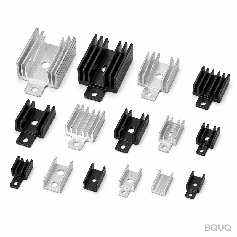
This is where the manufacturing route matters. Extruded profiles are economical and consistent along their length, but extrusion alone rarely holds tight flatness across a wide base — that usually needs a machining pass. Fully CNC-machined bases give you the flatness and finish control directly, at a higher unit cost. Many projects use an extruded body with a machined mounting face, which is a good cost-performance compromise. You can see the range of options on our heat sinks page.
Does the TIM type change the pressure target?
Yes, substantially. The compression behaviour of a material is a property of the material.
| TIM type | Typical bond line | Typical mounting pressure | Notes |
|---|---|---|---|
| Thermal grease | 0.02–0.08 mm | 10–30 psi | Low modulus, pumps out under cycling |
| Phase-change film | 0.03–0.10 mm | 20–50 psi | Thins at operating temperature |
| Soft gap filler pad | 0.10–0.50 mm | 5–20 psi | Very low modulus, tolerant of gaps |
| Standard silicone pad | 0.10–0.25 mm | 20–50 psi | Most common, well characterised |
| Cured thermal adhesive | 0.05–0.15 mm | Contact pressure during cure | Bond replaces fasteners |
Grease needs less pressure because it flows readily, but it also migrates. Pads need more pressure to wet out, but they stay put. Adhesives are a special case: you apply pressure only during the cure, and the bond line is then locked. That is covered in more depth in our article on thermal interface selection.
How do I verify the bond line after assembly?
You cannot see the interface, so verify indirectly. Three practical methods:
1. Thermal measurement. Run a known power load and measure case-to-sink delta. Compare against your predicted resistance. A delta far above prediction usually means poor contact, not a bad heat sink.
2. Teardown inspection. Disassemble a sample and look at the TIM imprint. Full, even coverage with slight squeeze-out at the perimeter is correct. Patchy coverage means low pressure or a bowed base. Heavy squeeze-out with bare metal showing means over-compression.
3. Pressure film or shim stock. Pressure-sensitive film between the surfaces shows the pressure distribution directly. A 0.05 mm shim that slides out easily marks a low-pressure zone.
Build a small sample set at 15, 30, and 45 psi, measure each, and plot the result. Most designs show a clear minimum somewhere in the middle of that range. That curve is worth more than any rule of thumb.
Accounting for the whole thermal path
The interface is one resistor in a chain. If the heat sink itself is undersized, no amount of mounting pressure will save the design. It helps to model the full path — spreading resistance, base conduction, fin convection — before you tune the interface. Our walkthrough of the thermal resistance network shows how to break that chain into measurable pieces. For larger modules, baseplate flatness and mounting architecture deserve their own treatment, as covered in our IGBT module baseplate notes.
Common mistakes that quietly ruin the bond line
- Specifying torque instead of pressure. Torque is a proxy. Thread friction varies with plating and lubrication, so the same torque can give 20% different force between two batches.
- Ignoring thermal cycling. Pads relax, grease pumps out, and differential expansion between aluminium and copper changes the gap. Spring-loaded mounting holds pressure far better than rigid screw-down.
- Mixing TIM thickness and pressure targets. A pad rated for 10 psi will not reach its rated performance at 40 psi.
- Bolting through an unsupported base. Thin bases deflect between screws. Add stiffening ribs or thicker mounting bosses.
- Forgetting the component side. The die, lid, or package baseplate is also part of the stack. Its flatness and stiffness set the upper bound on how uniform your pressure can be.
Where manufacturing tolerances enter the picture
Two identical heat sinks from two suppliers can behave differently in the same assembly if their base flatness or finish differs. That is why the drawing should specify flatness over the contact area, surface roughness, and the datum used for measurement — not just overall dimensions.
At BQUQ, CNC-machined bases hold ±0.005 mm on critical features and can be specified to 0.02–0.05 mm flatness across the mounting face. Extruded profiles give a lower unit cost for long, simple geometries, and we machine the interface where the thermal budget demands it. Four production lines in one Dongguan factory cover machining, stamping, springs, and heat sink assembly, so the mounting hardware and the heat sink can be qualified together rather than in isolation. Review the machined options on our CNC machined heat sinks page and the profile options on our extruded heat sinks page.
Send a drawing and a target pressure and we will quote in 12 working hours, with flexible MOQ for prototype and pilot builds.
Frequently Asked Questions
Q: What is a good mounting pressure for a thermal pad?
A: Most standard silicone pads perform best between 20 and 50 psi, where they compress to roughly 0.10–0.20 mm. Soft gap fillers are designed for lower pressures, often 5–20 psi. Always read the compression curve on the specific TIM datasheet, because modulus varies widely between products and the optimum is material-specific.
Q: Can too much mounting pressure make cooling worse?
A: Yes. Beyond roughly 50 psi, many materials are squeezed out of the mating zone, leaving bare metal contact at high points and coverage gaps. Bulk resistance stops falling and contact resistance rises. Excessive force also bows thin baseplates and can mechanically stress the component, so more pressure is not automatically better.
Q: How do I convert screw torque into mounting pressure?
A: Estimate force per screw from torque using the thread friction coefficient, then divide total force by the TIM footprint area. In practice, friction uncertainty makes this approximate. Pressure-sensitive film or a load cell on a sample assembly gives a far more reliable number, and spring washers help hold that pressure over time.
Q: Does heat sink flatness really affect thermal performance?
A: It does, and often more than material choice. A base bowed by 0.10 mm can leave the interface at 40 psi in the centre and near zero at the edges, so the TIM stays thick where you need it thin. Specifying 0.05 mm flatness for pads and 0.02–0.03 mm for high-power interfaces is a practical starting point.
Q: Should I use thermal adhesive instead of mechanical mounting?
A: Use adhesive when the joint is small, vibration is high, or fasteners are impractical. Adhesive removes the pressure-holding problem but makes rework difficult and sets the bond line permanently at whatever pressure you applied during cure. For serviceable, high-power assemblies, mechanical mounting with controlled pressure is usually the better choice.
Related Resources
- About BQUQ and our Dongguan production setup: /about/
- Heat sink product range, including extruded and machined options: /heat-sinks/
- Industry trends in electronics thermal management: /industry-dynamics/
- Technical articles on heat sink design and manufacturing: /bquq-blog/
- Frequently asked questions on sourcing and tolerances: /faq/
- Case studies from prototype to volume production: /case/
- Contact the engineering team for a 12-hour quote: /contact/
Authored by the BQUQ Engineering Team. BQUQ (Dongguan) runs CNC machining (±0.005 mm), metal stamping, custom springs, and heat sink production in one ISO9001 factory. Source-direct from Dongguan, China — quote in 12 hours: sc@bquq.com | WhatsApp +86 13713157787 | www.bquq.com


