
BQUQ explains LED junction temperature, how Tj controls L70 lifetime, Rth budgeting, and heat sink sizing for LED modules machined and stamped in Dongguan.
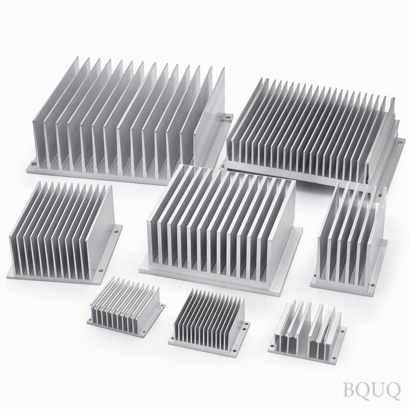
LED Thermal Management: Junction Temperature and Lifetime
Short answer: hold the LED junction below about 85–105 °C and most power LEDs deliver their rated L70 lifetime of 50,000–100,000 hours; run the junction 20–30 °C hotter and expected life can drop by half to two-thirds. Because LED light output and lifetime both degrade with temperature, junction temperature is the single number that links your thermal design to your warranty cost. A 50 W LED module at 50% efficiency dumps 25 W of heat into the heat sink, and that heat must move through a thermal budget of typically 0.5–2.5 K/W from junction to air.
LEDs are efficient compared with incandescent lamps, but they are not cold. A mid-power LED converts only 30–50% of input power to light, and the rest is heat generated in a chip a few square millimeters across. That makes the LED package one of the densest heat sources in electronics, and it is why junction temperature, not ambient temperature, is the number that decides how long the luminaire lives.
What Junction Temperature Actually Controls
The junction temperature Tj is the hottest point in the LED die. Three things respond to it. Light output falls with temperature, typically 3–10% luminous flux loss by the time the junction runs at 100 °C versus 25 °C. Color shifts: phosphor-converted white LEDs drift in CCT as the die heats. Lifetime collapses: lumen maintenance follows an Arrhenius-type acceleration, which is why industry lifetime figures are always quoted at a specific Tj. Most manufacturers publish L70 lifetime at a reference junction temperature such as 85 °C, and a common rule of thumb is that each 10 °C rise in Tj roughly halves the remaining life.
That last point deserves the emphasis. The difference between a well-sinked luminaire at Tj 75 °C and a marginal one at Tj 105 °C is not a subtle 30% effect. At the typical acceleration factor, the hot one can fail its L70 target in a fraction of the rated time, which is exactly how "100,000 hour" LED street lights end up dim in year three. Real lifetime claims come from LM-80 testing of the LED package and TM-21 extrapolation, and both are only valid at the junction temperature your heat sink actually delivers.
Building the Thermal Budget From Tj Down
Thermal design for an LED starts at the junction and works outward. The budget is:
Tj = Ta + P·(Rth j-c + Rth c-s + Rth s-a)
where P is the heat in watts, Ta ambient temperature, Rth j-c the package's junction-to-case resistance from the datasheet, Rth c-s the interface between LED package and heat sink, and Rth s-a the heat sink's case-to-ambient resistance. Worked example for a 30 W COB module running at 33% efficiency: 20 W of heat, Rth j-c of 0.5 K/W, a good thermal pad at 0.3 K/W, and you need the heat sink plus airflow to cover the rest.
| Component | Typical Rth (K/W) | Notes |
|---|---|---|
| LED package j-c (1–10 W power LEDs) | 2–8 | Higher for small packages |
| LED package j-c (COB modules) | 0.3–1.5 | Larger die, direct mount |
| TIM / thermal pad | 0.1–1.0 | Depends on thickness and pressure |
| Extruded heat sink, natural convection | 1.0–3.0 | Size and fin field dependent |
| Extruded heat sink, forced air | 0.3–1.0 | Fan required, noise trade |
| Heat sink plus heat pipe spreader | 0.2–0.6 | For high-power area sources |
Try the arithmetic at the extremes. A 20 W heat load, Rth j-c 0.5, pad 0.2, and a natural-convection sink at 1.5 K/W gives Tj = Ta + 20 × 2.2 = Ta + 44 °C. At 40 °C ambient, that is 84 °C at the junction, right at the comfort boundary. Bump the heat load to 30 W or the ambient to 55 °C for an enclosed street-light housing, and the same stack overshoots 100 °C. That is why LED heat sink selection is a calculation, not a size guess.
The Failure Modes Hot Junctions Cause
Junction temperature does not kill the die abruptly at a magic number, but several failure mechanisms accelerate with temperature. Phosphor degradation darkens white LEDs and shifts color. Solder fatigue at the die attach and at the board connection grows with thermal cycling amplitude, so a design that runs hot and cycles between day and night thermally stresses joints more than a steady warm one. Electrolytic capacitors in the LED driver age by roughly half per 10 °C rise. And in the worst case, a runaway failure: if the thermal path degrades, Tj climbs, efficiency drops, more input power becomes heat, and Tj climbs further.
Thermal runaway is the reason a heat sink for LED lighting is a safety component, not an accessory. For outdoor fixtures, anodized aluminum housings with sealed driver compartments are the norm; BQUQ machines and stamps these housings with machined LED mounting faces so the board-to-housing interface stays flat and thin, and we black-anodize them to improve radiative exchange. Small gains, but at the LED power densities above, every 2–3 °C saved at the case is real lifetime at the junction.
Sizing the Heat Sink From a Lifetime Target
The professional way to size an LED heat sink is backwards from the warranty. Decide the L70 lifetime you must deliver, read the LM-80/TM-21 data at that lifetime to find the maximum Tj, then solve the budget for the maximum Rth s-a the heat sink may have at your worst-case ambient and drive current. Typical outcomes:
| Application | Typical heat load | Typical target Tj | Resulting Rth budget |
|---|---|---|---|
| 5–10 W downlight | 3–7 W | ≤ 85–95 °C | 4–10 K/W |
| 30–50 W street light module | 20–35 W | ≤ 85–95 °C | 1.5–2.5 K/W |
| 100–200 W high-bay | 60–140 W | ≤ 90–105 °C | 0.4–0.9 K/W (forced air) |
| COB track head, 40 W | 25–30 W | ≤ 85–95 °C | 1.2–2.0 K/W |
These are indicative budgets, not quotes. Two real-world corrections push most designs harder than the simple math: the heat sink base spreads heat from a small board, and real fins are not 100% efficient, which is why you should run the numbers with the fin efficiency and thermal resistance methods covered elsewhere. Ambient inside an enclosed fixture is also 10–20 °C above room temperature, so design on internal ambient, not the air outside the housing.
Checking a Supplier's Thermal Numbers
A credible LED heat sink quotation states its conditions. Look for the heat load in watts at which the resistance is quoted, the ambient temperature, whether the number includes a TIM and which one, and the orientation of the fins. A figure measured at 25 °C ambient with an ideal pad will not survive a 55 °C internal fixture temperature, and the shortfall is not the supplier's fault, it is the specification's. Ask the same question every way: what worst case does this sink meet, not what best case was it measured at?
The second check is the spreading story. LED boards are small relative to housings, so ask what source footprint and base thickness the design assumes. A thin housing wall behind a COB module adds a spreading penalty that no fin count reveals; a machined pad, a thicker local boss, or an embedded copper slug fixes it. If the supplier cannot state the assumed source size, the thermal analysis has not been done, and the first field failure will teach the difference at your cost.
Lifetime claims deserve the same scrutiny. If the fixture is warranted for 50,000 hours, ask what junction temperature the design holds at the worst-case drive current and ambient, and compare it with the LM-80/TM-21 data of the actual LED. A design that clears the junction limit by 5 °C is fragile; one with 15–25 °C of margin survives dust loading, driver tolerance and a hot summer. The margin is where the metal is spent, and it is cheaper to spend it in the extrusion than in the warranty reserve.
At BQUQ the LED housings and heat sinks we machine start from the module drawing: a flat mounting pad, a fastener pattern for uniform pressure, wall thickness sized to spread the heat, and black anodizing to add radiation on passive fixtures. Holding the pad flat to ±0.005 mm and machining the boss and fins from the same billet keeps the thermal path short and the interface thin. Send the LED module datasheet, driver current and ambient to sc@bquq.com or WhatsApp +86 13713157787, and the 12-hour quote will state the conditions the design meets.
Frequently Asked Questions
Q: What is a safe junction temperature for power LEDs?
A: For most power LEDs, keeping Tj at or below 85–105 °C preserves rated L70 lifetime; many datasheets specify lifetime at Tj 85 °C. Above roughly 110–120 °C, lumen maintenance and phosphor life degrade quickly and thermal runaway risk rises.
Q: How do I measure LED junction temperature?
A: The standard method is electrical: forward voltage of the LED is calibrated against temperature at a low sense current, then measured at operating current to infer Tj. Alternatively, estimate with Tj = Ta + P × total Rth using datasheet values, or spot-check the case with a thermocouple and add the datasheet's j-c drop.
Q: Why does my LED heat sink feel only warm if the junction is hot?
A: Because the thermal budget is a ladder. If the case-to-air resistance is high, most of the temperature rise is inside the package and the sink stays cool while the junction cooks. A cool heat sink on a hot LED usually means the interface or the package path is the bottleneck, not too little sink.
Q: What is L70 lifetime and why is it tied to temperature?
A: L70 is the hours until the LED emits 70% of its initial lumens, extrapolated from LM-80 data via TM-21. Lumen degradation is thermally accelerated, so L70 is always quoted at a junction temperature; run the junction hotter and the same LED reaches 70% output far sooner.
Q: What thermal specifications should I send with an LED heat sink inquiry?
A: Send LED power and efficiency or heat load in watts, worst-case ambient, target Tj or L70 hours, board size and mounting pattern, and whether airflow is allowed. BQUQ uses that to machine a sink and quote within 12 working hours: sc@bquq.com or WhatsApp +86 13713157787.
Related Resources
- LED Heat Sink Selection Guide — matching sink geometry to LED modules and drivers.
- CNC-machined heat sinks — machined mounting faces, tapped holes and anodized housings for LED fixtures.
- About BQUQ — an ISO9001-certified source factory in Dongguan running CNC, stamping, spring and heat sink lines under one roof.
- Contact us — send your drawing for a quote within 12 working hours.
Authored by the BQUQ Engineering Team. BQUQ is an ISO9001-certified source factory in Dongguan, China, running CNC machining, metal stamping, custom springs, heat sink and collet lines under one roof. Send drawings to sc@bquq.com or WhatsApp +86 13713157787 for a quote within 12 working hours. www.bquq.com


