
IGBT heat sink sizing: conduction and switching losses, resistance budgeting, forced-air numbers. BQUQ (ISO9001, Dongguan) quotes in 12 hours.
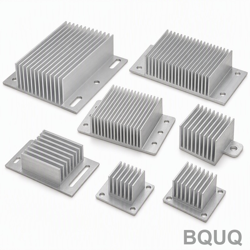
Cooling IGBT and Power Modules: Heat Sink Sizing for High Current
A 1200 V IGBT module carrying 200 A per switch typically dumps 350-700 W of heat per half-bridge, and its heat sink must hold case temperature low enough that junction temperature stays under the 125 °C design point — which usually means a required sink-to-ambient resistance below 0.05 K/W and forced air as standard. At these power densities, natural convection is not an option; the engineering question is how much finned extrusion, how much airflow, and when to move to liquid.
Power modules are the opposite of small-signal electronics: losses are big, heat flux is high, and the thermal path is short and precious. The junction-to-case resistance inside the module is small — often 0.03-0.1 K/W — so the case-to-ambient side, meaning your heat sink and airflow, dominates the temperature budget. If you size that wrong, the module's own over-temperature protection shuts your drive down at the worst moment. Here is how the calculation actually runs.
Step 1: Count Both Kinds of Losses
IGBT losses come in two flavors. Conduction loss is the saturation voltage times the current times the duty cycle: Pcond = Vce(sat) × I × duty. Switching loss is the turn-on and turn-off energy per cycle times the switching frequency: Psw = (Eon + Eoff) × fsw. Both sit in the datasheet, and both scale with current and voltage class.
| Parameter | 600 V class IGBT | 1200 V class IGBT |
|---|---|---|
| Vce(sat) at rated current, 25 °C | 1.5-1.9 V | 1.7-2.2 V |
| Eon + Eoff per cycle (typical, 25 °C) | 2-6 mJ | 10-40 mJ |
| Max junction temperature | 150 °C | 150 °C |
| Typical design junction limit | 125 °C | 125 °C |
Takeaway: at low switching frequency, conduction dominates and a lower-saturation module wins; at high frequency, switching losses take over and the module choice plus gate drive matter more than the sink. Either way, the sink sees the sum, so compute both before sizing anything.
Step 2: Worked Sizing Example at 200 A
Consider a drive phase using 1200 V modules switching at 5 kHz with 200 A rms through each IGBT and 50% duty. Conduction: 1.9 V × 200 A × 0.5 ≈ 190 W per switch. Switching: 35 mJ per cycle at 5 kHz ≈ 175 W per switch. Each IGBT dissipates roughly 365 W; a half-bridge module with two switches and their diodes runs near 800-900 W total. That is the heat a real industrial drive leg must move.
| Budget item | Value |
|---|---|
| Ambient (worst case cabinet) | 40-50 °C |
| Design junction temperature | 125 °C |
| Module Rth junction-to-case | ~0.05-0.08 K/W |
| Case-to-sink (TIM + flatness) | ~0.02-0.05 K/W |
| Remaining budget for sink-to-air | 0.03-0.06 K/W |
Takeaway: with roughly 800 W and only ~70-80 K of usable rise, the sink-to-ambient resistance must sit near 0.04-0.06 K/W. A passive extrusion cannot deliver that — at natural-convection coefficients you would need several square meters of fin surface. Forced air at 3-6 m/s through a properly ducted profile gets there with a realistic footprint.
Step 3: Choose the Cooling Regime by Power Density
The regime table below is the practical selector used on most power-electronic designs. Small modules and low losses can survive natural convection; everything above a few hundred watts per module moves to forced air, and high-density stacks go liquid.
| Dissipated power per module | Typical regime | Sink requirement |
|---|---|---|
| Under ~100 W | Natural convection, generous fins | 0.3-1.0 K/W |
| 100-300 W | Forced air, 2-4 m/s | 0.1-0.3 K/W |
| 300-1000 W | Ducted forced air, 3-6 m/s | 0.02-0.1 K/W |
| Above ~1 kW or high ambient | Liquid cold plate | 0.005-0.02 K/W |
Takeaway: the crossing points are soft but honest — the moment your calculation asks for under ~0.1 K/W from a passive sink, stop adding fins and start adding a fan and a duct. Every extra m/s of velocity is worth more than another 100 mm of aluminum.
The Module-to-Sink Interface Is Where Designs Fail
Power modules waste more cooling at the interface than anywhere else. The baseplate must sit flat on the sink base: module baseplate flatness is typically specified within 0.05 mm, and the sink mounting surface should match or beat it — that is where CNC-machined sink bases earn their keep, holding the contact face flat so the TIM works. CNC-machined heat sinks with a milled, flat baseplate pocket are standard for high-power modules precisely for this reason.
Interface rules that actually matter: use a thermal pad or grease rated for the module's voltage isolation requirements (many modules need isolation between baseplate and sink), apply the manufacturer's mounting torque in the specified sequence, and never omit the TIM because the surfaces "look flat." A dry joint can add 0.1-0.3 K/W and quietly raise junction temperature by 30-50 K at 500 W.
Ducting Beats Bigger Fins in Forced Air
A fan blowing at an open fin block wastes a large share of its air around the edges. Shroud the fan to the fin block so all airflow is forced through the channels, and keep the outlet clear — a ducted 3 m/s flow routinely outperforms an unducted 5 m/s blast. Watch the pressure drop: dense fins at 2-3 mm gap are tempting for surface area, but if the fan stalls, the module runs hotter than with wider fins and honest airflow.
Two shop-floor checks: measure air temperature rise across the sink (it should be well under ~15-20 K at full load in a well-sized design), and verify the sink base temperature with a thermocouple against your calculated case temperature. If base temperature is not close to prediction, the interface — not the fins — is the suspect.
When to Machine Instead of Extrude
Extruded profiles are the default for power module sinks because cost per watt of cooling is lowest at volume, and a 400-800 mm long extruded heat sink with a thick base carries a row of modules beautifully. But modules come with odd hole patterns, buried mounting inserts, or stepped baseplates; that is where CNC machining adds the pockets, counterbores, and precise base flatness that an as-extruded profile cannot provide. The heat sink types guide covers when each process wins, and a factory that runs both — like ours in Dongguan — can quote the same part both ways so you see the real crossover.
Email sc@bquq.com or WhatsApp +86 137 1315 7787 with your PDF/DXF/STEP file. An engineer reviews it and replies with price, lead time and DFM notes on working days.
Frequently Asked Questions
Q: How much heat does an IGBT module actually dissipate at high current?
A: Add conduction loss (Vce(sat) × current × duty) to switching loss (switching energy × frequency). A 1200 V module at 200 A and 5 kHz lands around 350-400 W per switch, so a full half-bridge with diodes can exceed 800 W — that is the number the sink must move.
Q: What heat sink thermal resistance does a 600 W power module need?
A: With 125 °C design junction, 50 °C ambient, and roughly 0.1 K/W inside the module and interface, the sink-to-air budget lands near 0.03-0.05 K/W. That requires ducted forced air at 3-6 m/s over a large finned extrusion — passive cooling cannot reach it.
Q: Can I cool an IGBT module with natural convection?
A: Only below roughly 100 W of module dissipation. Above that the required sink-to-ambient resistance drops below about 0.2-0.3 K/W, which passive fins cannot deliver in any practical envelope. Add a fan and a duct before you add more fin area.
Q: Why does baseplate flatness matter so much for power module heat sinks?
A: Module baseplates and sink faces are speced within ~0.05 mm flatness so the thermal interface layer stays thin and uniform. A bowed contact face thickens the TIM locally, adding 0.1-0.3 K/W that can push junction temperature 30-50 K higher at full load.
Q: When should I move from forced air to liquid cooling for IGBTs?
A: When dissipation passes roughly 1 kW per module, or when ambient is high and airflow is restricted by the enclosure. Liquid cold plates reach 0.005-0.02 K/W, several times better than any air-cooled fin block of comparable size.
Related Articles
- heat-sink-types-extruded-vs-cnc-vs-stamped-vs-skived — More from the BQUQ Thermal Management engineering series.
- air-cooling-vs-liquid-cooling-electronics — More from the BQUQ Thermal Management engineering series.
- led-heat-sink-selection-guide — More from the BQUQ Thermal Management engineering series.
Data Sources and Verification
Tolerances, cycle times and price ranges in this guide come from BQUQ production records at our Dongguan plant, where CNC machining (±0.005 mm), stamping, custom springs and heat sinks run under one roof. BQUQ is an ISO 9001:2015 certified factory; the certificate and batch inspection reports are available on request with every quotation.
Related Resources
- About BQUQ: an ISO9001-certified source factory in Dongguan running four production lines under one roof.
- Heat sinks and thermal parts: extruded, CNC-machined and stamped options from the thermal line — extruded heat sinks, CNC-machined heat sinks, stamped heat sinks.
- Industry trends: manufacturing, material market, and sourcing analysis for buyers.
- Technical articles: engineering guides and process comparisons — more where this article came from.
- FAQ hub: quick answers on CNC, stamping, springs, and heat sinks.
- Case studies: real parts and real numbers from projects we engineered and delivered.
- Contact us: send your drawing and get a quote within 12 working hours.
Authored by the BQUQ Engineering Team. BQUQ is an ISO9001-certified source factory in Dongguan, China, running CNC machining, metal stamping, custom springs and heat sink lines under one roof. Send drawings to sc@bquq.com or WhatsApp +86 13713157787 for a quote within 12 working hours. www.bquq.com


