
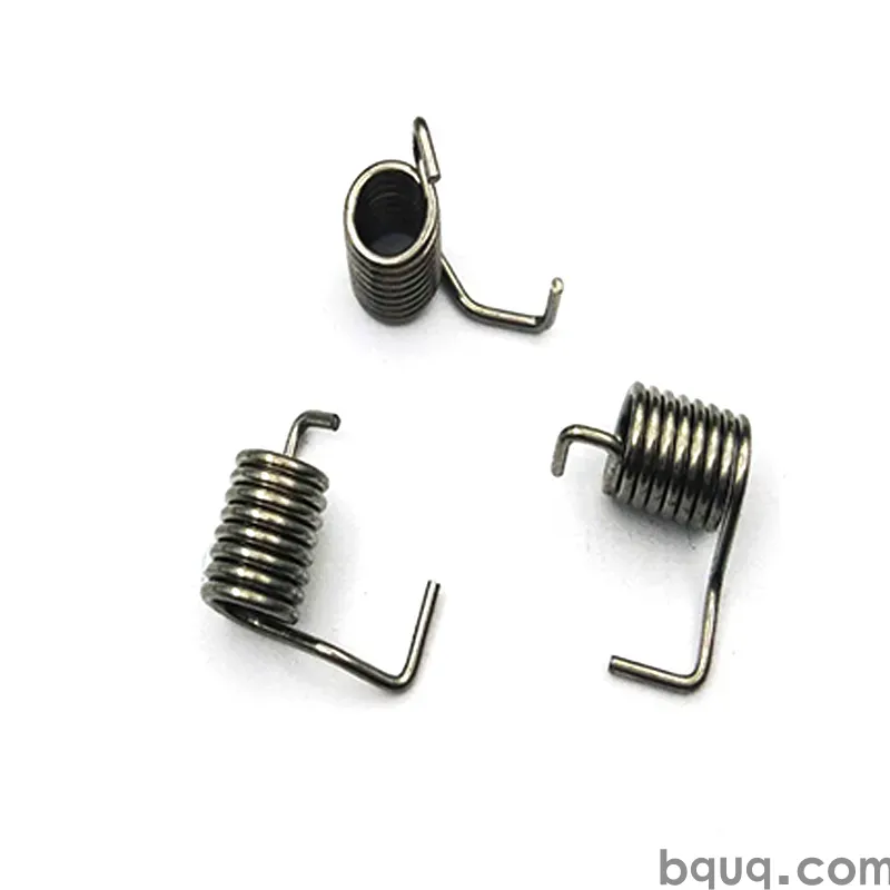
Spring Failure Analysis: Reading a Broken Spring
Short answer: A broken spring is a document. The fracture face tells you the failure mode: a flat 45° shear lip points to overload or a single event; a smooth, polished zone with concentric beach marks points to fatigue; a dark, pitted surface with multiple origins points to corrosion fatigue; a brittle, intergranular crack with no deformation points to hydrogen embrittlement or a heat-treatment defect. Read the origin, the direction of crack propagation, the surface condition, and the wire diameter reduction at the break — then match it against the load history. Most field failures we see at BQUQ resolve into four families: fatigue, corrosion, overload, and embrittlement.
Why Should You Bother Reading a Broken Spring?
Because the same spring geometry fails for completely different reasons, and the fix is different every time. If you replace a fatigue-broken spring with the same part in a stronger wire, you often move the failure to a different coil. If you replace a corrosion-broken spring with a thicker one, you simply give the pits more area to nucleate from.
A broken spring is physical evidence of a stress state your design or your application produced. It is the cheapest test data you will ever get — you already paid for it with a field failure. Reading it correctly turns a warranty claim into a design change.
At BQUQ we produce compression, torsion, and extension springs on dedicated CNC coiling and forming lines in one Dongguan factory, with ±0.005 mm CNC support for the mating hardware. When a customer sends us a fractured spring, the first thing we do is not measure it — we photograph the fracture face under magnification and ask for the load history.
What Are the Four Main Spring Failure Modes?
Almost every spring fracture falls into one of four families. Each has a signature.
| Failure mode | Fracture appearance | Typical origin | Key driver |
|---|---|---|---|
| Fatigue | Smooth polished zone + beach marks + final rough tear | Highest-stress coil, often first active coil | Cyclic stress range, stress concentration |
| Corrosion fatigue | Pitted, dark, multiple crack origins | Surface pits, salt spray, condensation | Chlorides, humidity, coating damage |
| Overload / yield | 45° shear lip, necking, wire diameter reduction | Point of maximum moment | Single event, bottoming, over-travel |
| Embrittlement / brittle | Flat, granular, no deformation, intergranular path | Grain boundaries, plated parts | Hydrogen, poor tempering, high hardness |
Fatigue: The Beach-Mark Signature
A fatigue fracture has two zones. The first is the initiation and propagation zone — smooth, often polished by the two faces rubbing together, sometimes showing concentric "beach marks" or "clamshell" rings that map each load cycle. The second is the final fracture zone — rough, dull, sometimes 45° to the wire axis, because the remaining cross-section tore in one overload event.
The ratio of smooth zone to rough zone tells you the stress level. A large smooth zone with a small final tear means low nominal stress and many cycles — a classic high-cycle fatigue failure. A small smooth zone with a large tear means the spring was already close to its limit and failed in relatively few cycles.
Where the origin sits matters too. If it starts on the inside of the coil (the compression side), you are probably looking at residual stress from coiling or a stress concentration at a tool mark. If it starts on the outside diameter, check for contact with a bore, a burr on a mating part, or fretting.
Corrosion Fatigue: When Pits Become Cracks
Corrosion and fatigue are not additive — they are multiplicative. A pit is a stress raiser with a sharp tip, and it removes the protective compressive surface layer. A spring that would survive 10 million cycles dry can fail in 200,000 cycles in a chloride environment.
Look for:
- Multiple crack origins along the same wire, not one
- Dark or rust-colored staining inside the fracture
- Pitting on the wire surface away from the break
- Failure at a location where condensation would collect
This is the most common failure we see on springs used outdoors, in marine air, or in wash-down equipment. Stainless steel helps but does not solve it — 302 and 304 stainless are susceptible to chloride pitting. For chloride-rich environments, 17-7PH or a coated carbon steel with a proper barrier coating is often the better answer.
Overload: The 45° Shear Lip
An overload fracture is a single event. The wire yields, necks down, and separates on a plane roughly 45° to the tensile axis — the plane of maximum shear stress. You will see:
- Visible diameter reduction near the break
- A dull, fibrous, or sometimes cup-and-cone appearance
- No beach marks, no polished zone
- Often a bent or permanently set spring body
Common causes: the spring was compressed to solid height, an assembly forced it past its rated travel, a shock load arrived, or the spring was simply undersized for the load. Check the free length and the solid height against the application. If the spring arrived at solid height during service, the coils were touching and the effective stress went up sharply.
Embrittlement and Brittle Fracture
Brittle fracture shows no plastic deformation at all. The faces fit together cleanly. Under a microscope the crack path follows grain boundaries (intergranular) rather than cutting through grains. This is the signature of hydrogen embrittlement, which typically appears on high-strength steel springs that were electroplated (zinc, cadmium, chrome) without a proper post-plate bake.
It can also come from a heat-treatment problem: over-tempering, insufficient tempering after quench, or a decarburized surface layer. Decarburization removes carbon from the surface, lowering the fatigue strength exactly where the stress is highest.
Rule of thumb: if a plated spring breaks within 24 to 72 hours of plating or within the first few cycles after assembly, suspect hydrogen. If it breaks after weeks of service with no deformation, suspect a material or heat-treatment issue.
How Do You Read the Fracture Face Step by Step?
Work through this sequence. It takes about ten minutes and it will save you a redesign cycle.
Step 1: Photograph Before You Touch
Photograph the fracture face at 10× to 30× before you handle it. Handling smears the surface and destroys the fine features you need. Note the position of the break relative to the ends: first active coil, middle, or end coil.
Step 2: Identify the Origin
The origin is where the smooth zone converges. Trace the beach marks backward — they point to the origin. Mark it. Then look at what is directly under the origin: a tool mark, a pit, an inclusion, a contact point, a sharp radius.
Step 3: Measure the Wire at the Break
Measure the wire diameter 2 mm from the fracture on both sides, and at the fracture itself. Any reduction means plastic deformation — that is an overload signature. No reduction means brittle or fatigue.
Step 4: Check the Surface Away From the Break
Look at the rest of the spring. Pitting, fretting wear, coating damage, or a rubbed flat spot all tell you what the spring was touching. Fretting at the coil contact points is a common fatigue initiator in compression springs.
Step 5: Match Against the Load History
Now compare what you see with what the spring was supposed to do.
| Observation | Likely cause | First corrective action |
|---|---|---|
| Origin at first active coil, smooth zone large | High-cycle fatigue at peak stress | Reduce stress range, shot peen, increase wire |
| Multiple origins, pitting, staining | Corrosion fatigue | Change material or coating, add drainage |
| Diameter reduction, 45° lip | Overload / solid height | Increase travel clearance, resize spring |
| No deformation, intergranular, plated | Hydrogen embrittlement | Bake after plating, switch to mechanical plating |
| Origin at a tool mark or sharp radius | Stress concentration | Improve coiling tooling, add radius |
| Fretting flats at coil contacts | Contact fatigue | Change end configuration, add separators |
What Does the Spring's Position Tell You?
The location of the break is nearly as informative as its appearance.
Break at the first active coil from the end. This is the highest-stress coil in most compression springs because it carries the full load with the least support. It is the classic fatigue location. If your spring consistently breaks here, you have a stress problem, not a material problem.
Break at the end coil or the closed end. Usually a manufacturing or assembly issue — a sharp transition from the closed end to the active coil, a burr, or a bending stress introduced during installation.
Break in the middle of the body. Often a defect origin: an inclusion, a seam in the wire, a scratch from handling, or a corrosion pit. Check the wire lot.
Break on a torsion spring leg. Torsion springs almost always fail at the leg bend or the first coil adjacent to the leg, because that is where bending stress concentrates. Leg design matters enormously here — a sharp inside radius on the leg is a crack starter.
Break on an extension spring hook. The hook-to-coil transition is the weak point. If the hook was formed with a sharp radius or the wire was nicked during forming, failure starts there.
How Do You Prevent the Failure From Repeating?
Once you have a diagnosis, the fix usually falls into one of five buckets.
Reduce the Stress Range
The single most effective lever. Fatigue life scales roughly with the inverse of stress range to a power of 3 to 5 for steel springs. A 10% reduction in stress range can multiply life several times over. That means a larger wire, more coils, a longer free length, or a lower installed load.
Add Shot Peening
Shot peening puts the surface into compressive residual stress, which closes crack initiation. It is one of the highest-value-per-cost treatments available for fatigue-critical springs. For high-cycle applications it is close to mandatory.
Fix the Corrosion Path
Choose the material for the environment, not for the drawing. In chloride environments, consider 17-7PH or a properly coated carbon steel. Add drainage so water does not sit in the spring pocket. Avoid mixing dissimilar metals that create a galvanic couple.
Control the Plating Process
If the spring is high-strength steel and electroplated, specify a post-plate bake. Better still, move to mechanical plating or a non-electrolytic coating for high-hardness parts. This is a process control issue, not a design issue, and it is one of the most common causes of "mystery" early failures.
Improve the Manufacturing Detail
Radius the leg bends. Remove tool marks. Control the coiling stress. Specify the wire surface condition. Keep the spring clean — contamination and handling damage are real initiators. And if the spring runs hot, consider a hot preset or stress-relief cycle to stabilize the geometry.
Frequently Asked Questions
Q: Can I tell fatigue from overload without a microscope?
A: Yes, in most cases. Fatigue leaves a smooth, polished propagation zone with beach marks and a rough final tear, and the wire diameter at the break is essentially unchanged. Overload leaves visible diameter reduction, a 45° shear lip, and a dull fibrous face with no polished zone. A 10× loupe or a phone macro lens is usually enough to separate the two.
Q: Why did my plated spring break within a day of assembly?
A: That timing is the classic hydrogen embrittlement signature. High-strength steel absorbs hydrogen during acid pickling and electroplating; if it is not baked out promptly, the hydrogen collects at grain boundaries and cracks under load. The fix is a post-plate bake within the specified window, or switching to mechanical plating or a non-electrolytic coating.
Q: Does switching to stainless steel stop corrosion failures?
A: Not automatically. 302 and 304 stainless resist general rust but are still vulnerable to chloride pitting, which is exactly what drives corrosion fatigue in marine and wash-down environments. For chloride-rich service, consider 17-7PH or a carbon steel with a robust barrier coating, and design drainage so water cannot pool around the spring.
Q: How much does shot peening actually improve spring life?
A: It depends on the application, but for high-cycle steel springs the improvement is often substantial — frequently a multiple of the untreated life rather than a marginal gain. The mechanism is compressive residual stress at the surface, which suppresses crack initiation. It is most effective when the failure origin is a surface feature rather than an internal inclusion.
Q: What information should I send for a failure analysis?
A: Send the broken spring with both fracture halves if possible, the drawing and material spec, the application load and travel, the cycle count to failure, the environment, and photos of the installed position. That package usually lets us identify the mode and recommend a corrective change. BQUQ quotes replacement or revised springs within 12 working hours.
Related Resources
- About BQUQ and our Dongguan production footprint: /about/
- Custom compression springs: /compression-springs/
- Torsion springs and leg design: /torsion-springs/
- Extension springs and hook configurations: /extension-custom-springs/
- Industry trends in spring sourcing and lead times: /industry-dynamics/
- More technical articles on spring design and failure: /bquq-blog/
- Frequently asked questions on quoting and MOQ: /faq/
- Case studies from our spring and stamping lines: /case/
- Contact the engineering team: /contact/
Authored by the BQUQ Engineering Team. BQUQ (Dongguan) runs CNC machining (±0.005 mm), metal stamping, custom springs, and heat sink production in one ISO9001 factory. Source-direct from Dongguan, China — quote in 12 hours: sc@bquq.com | WhatsApp +86 13713157787 | www.bquq.com


