
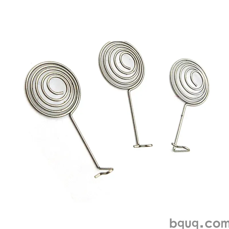
Stamped Pins and Terminals: Press-Fit and Solder Designs
Short answer: stamped pins and terminals are run on progressive dies from 0.10–3.0 mm strip, normally in brass, phosphor bronze, or beryllium copper. Press-fit designs hold with an interference band of roughly 0.05–0.15 mm in a plated through-hole and need elastic spring-back; solder designs need a wettable, heat-tolerant surface and a compliant lead. Choose the joint method first — geometry, material and plating all follow from it. BQUQ stamps both types in Dongguan and holds ±0.05 mm on strip features.
Stamped pins and terminals are the connective tissue of electronics. They carry current from a connector to a board, from a battery to a contact, from a fuse to a busbar. They are cheap to make in volume, which is exactly why the design details matter: a cent or two of extra strip per piece, multiplied by two million pieces, is real money. This guide covers the two dominant joint methods — press-fit and solder — and how each one changes the design, the material, and the tolerance you should call out. If you want the wider picture of the part family, start with our custom stamped parts guide.
Press-Fit vs Solder: Pick the Joint Before the Geometry
The single biggest mistake buyers make is treating press-fit and solder pins as the same part with a different finish. They are not. A press-fit pin is a spring. It is designed so that when it is pushed into a hole slightly smaller than its widest band, the metal deflects elastically and pushes back against the barrel wall. That normal force holds the part in place and creates the electrical interface. It must survive insertion, must not yield permanently, and must keep its contact force through thermal cycling.
A solder terminal does the opposite job. It does not need to hold itself mechanically — solder does that. It needs to present a surface the alloy can wet, tolerate reflow temperatures without losing plating integrity, and provide a compliant lead or foot that absorbs the small mismatches between the terminal and the pad. A pin optimized for press-fit makes a poor solder joint, and a solder foot pressed into a hole will not hold. Pick the joint, then design.
A useful anchor: press-fit is for boards you do not want to reflow, high-current paths, and field-serviceable connectors. Solder is for SMT or through-hole reflow lines where the terminal is one of many components on the panel. Mixed populations exist, but they are usually two different part numbers.
Materials and Plating for Pins and Terminals
| Base material | Typical use | Conductivity vs copper | Notes |
|---|---|---|---|
| Brass (H65/C2600) | General terminals, low-cost pins | ~28% IACS | Easy to stamp and plate, moderate spring |
| Phosphor bronze (C51000) | Press-fit pins, contacts | ~15% IACS | Good spring, resists stress relaxation |
| Beryllium copper (C17200) | High-cycle press-fit, relays | ~22% IACS | Best spring and fatigue life, higher cost |
| Copper alloy (C194) | Lead frames, high-current pins | ~60% IACS | Excellent conductivity, moderate strength |
| Stainless 301/304 | Shielding, non-current clips | Low | Corrosion resistance, poor conductivity |
Plating is chosen by joint method and environment. Tin (1–3 µm, matte or bright) is the workhorse for solder terminals because it wets readily and is low cost. Selective gold (0.05–0.8 µm over 0.5–1.5 µm nickel) is standard for press-fit pins and for contacts that must survive many mating cycles or carry low-voltage signals where oxide films matter. Silver is used on high-current contacts and fuse clips. Nickel underplate matters: it blocks diffusion between the base metal and the top finish and keeps the surface stable over time.
| Joint method | Common plating | Thickness guide | Why |
|---|---|---|---|
| Solder (SMT/THT) | Matte tin | 5–10 µm | Wettability, low cost |
| Solder (fine pitch) | Tin or Ni/Pd/Au | 1–3 µm tin | Thermal stability |
| Press-fit | Gold over nickel | 0.4–0.8 µm Au | Stable contact resistance, wear |
| Press-fit (cost-down) | Tin over nickel | 2–5 µm | Acceptable for few insertions |
| High-current | Silver over nickel | 2–5 µm | Low resistance, arc tolerance |
We keep the plating selection honest: if your insertion count is under five and your voltages are ordinary, gold is often money thrown away. If the pin carries a low-level analog signal or sees hundreds of mating cycles, tin will bite you. Tell us the cycle count and the current, and we will tell you the finish that fits. More on finishing options in our finishing stamped parts guide.
Geometry Rules for Press-Fit Pins
Press-fit success lives in three numbers: the interference band, the lead-in chamfer, and the compliance length.
| Feature | Typical range | Effect if wrong |
|---|---|---|
| Hole diameter | 0.6–1.0 mm | Sets insertion force |
| Interference | 0.05–0.15 mm | Too little = loose; too much = barrel damage |
| Lead-in chamfer | 0.2–0.5 mm, 15–30° | Missing = board damage, misalignment |
| Compliant length | 1.5–3.0 mm | Short = no spring; long = buckling |
| Plating thickness | 0.4–0.8 µm Au | Thin = wear-through |
The eye-of-the-needle and split-pin shapes are the two common compliant designs. Both rely on the pin being able to deflect without permanent set. That is why phosphor bronze or beryllium copper is used rather than brass: brass takes a set after a few insertions and the contact force decays. If your drawing calls a brass press-fit pin, expect retention force to drop after a handful of reworks.
Tolerance on the band width is the cost driver. A ±0.05 mm band holds most designs; pushing to ±0.02 mm on a 2 mm-wide band starts to demand better strip and tighter die maintenance. We hold ±0.05 mm as standard on strip features and will flag when a drawing asks for something the die cannot hold economically. See our metal stamping tolerances guide for the full breakdown.
Design Checklist for Solder Terminals
The solder terminal is a thermal and wetting problem more than a mechanical one. Points worth locking down before you release a drawing:
- Foot geometry: gull-wing and J-leads self-center during reflow; a straight through-hole prong does not.
- Solderable area: keep the wetted pad clear of plating-over-mold and of the die shear burr on the underside.
- Heat path: thin, long terminals conduct heat away from the joint and starve it; keep the lead section short and the cross-section adequate.
- Thermal relief: on a grounded pad, a direct connection to a large copper plane wicks heat and causes cold joints. Use relief spokes.
- Coplanarity: for SMT terminals, call out coplanarity — usually 0.1 mm max for a small pin, tighter for fine pitch.
Solder terminals are frequently combined with a crimp barrel on the wire side, which is why many parts are described as crimp-solder tabs. That hybrid is covered in our crimp and solder tabs article.
Tooling, Tolerances and Testing
Both pin families run on progressive dies, which means the same die produces the pin, the carrier strip, and the cutoff in one pass. Features under 0.3 mm demand fine-edge tooling and careful burr control, because the burr on a press-fit band changes the effective interference. Expect first-article inspection on the band width, the chamfer angle, and the plating thickness, plus a retention-force pull test on a plated coupon for press-fit parts. For solder terminals, solderability testing (wetting balance or dip-and-look) belongs in the PPAP package if your customer requires it. Our stamping inspection methods article walks through the gauges and frequencies.
Tooling is a one-time cost. A simple single-row pin die is economical; a multi-row die that produces eight terminals per stroke spreads the tooling across more parts and is the right call once volume justifies it. For prototype quantities we can also supply parts off a soft die or, for simple shapes, a laser-cut and formed sample, so you can validate fit before committing to hard tooling. Material selection interacts with all of this — a stiffer alloy stamps with more spring-back and may need a different forming station, which is why we confirm strip grade before finalizing the die layout. If you are still choosing the alloy, our stamped terminal materials article compares the common grades side by side.
Frequently Asked Questions
Q: What is the difference between a press-fit pin and a solder pin?
A: A press-fit pin holds itself mechanically by elastic interference in a plated hole and needs good spring properties; a solder pin is held by the joint and needs a wettable, heat-tolerant surface and a compliant lead. The two demand different materials and geometry and are normally separate part numbers.
Q: Which material is best for stamped terminals?
A: Brass for low-cost, low-current terminals; phosphor bronze for press-fit pins and contacts that must hold spring force; beryllium copper for high-cycle or relay contacts; copper alloy C194 for high-current lead frames. Selection follows current, insertion cycles and cost target.
Q: How much gold plating do press-fit pins need?
A: Typically 0.4–0.8 µm of gold over 0.5–1.5 µm of nickel. That range survives the insertion cycles and keeps contact resistance stable. Thinner gold wears through on repeated mating; thicker gold rarely pays back outside harsh environments.
Q: Can BQUQ stamp pins with selective plating?
A: Yes. We run selective gold, tin and silver plating on stamped strips and can plate only the contact zone to save cost while keeping the solderable or press-fit area specified. Send the drawing and plating callouts for a quote.
Q: What tolerance can you hold on stamped pin features?
A: ±0.05 mm on strip features is our standard, with ±0.02 mm available on critical bands when the die and strip support it. We flag any callout that would push cost steeply before quoting, rather than quoting it quietly.
Related Resources
- Stamped Terminal Design Guide — terminal geometry, plating and material selection for connectors and contacts.
- Stamped Terminals and Contacts — precision stamped terminals, pins and contacts produced on progressive dies in Dongguan.
- About BQUQ — an ISO9001-certified source factory running stamping, CNC, springs and heat sinks under one roof.
- Contact us — send a drawing to sc@bquq.com or WhatsApp +86 13713157787 for a quote within 12 working hours.
Authored by the BQUQ Engineering Team. BQUQ is an ISO9001-certified source factory in Dongguan, China, running CNC machining, metal stamping, custom springs, heat sink and collet lines under one roof. Send drawings to sc@bquq.com or WhatsApp +86 13713157787 for a quote within 12 working hours. www.bquq.com


