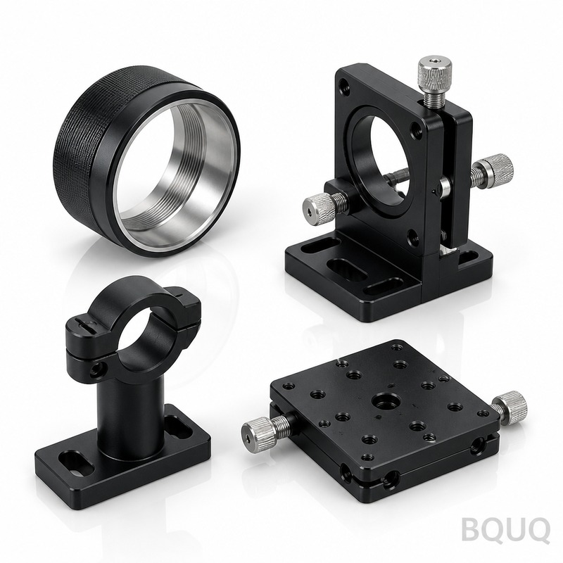
Optical Instrument Mount CNC Machining: 6061-T6 Aluminum, ±0.005mm Hole Positions, Ra0.8, Black Anodized
An optical mount for a metrology instrument lives or dies by two things: hole position and surface stability. The mounting holes that locate the optical axis must land within a few microns of print, and the anodized surfaces must not scatter light or shift dimensionally over temperature. Add monthly volumes in the hundreds with rolling engineering changes, and the sourcing problem becomes harder than the machining problem itself.
Project Background & Challenge
Our customer is a European OEM that builds semiconductor inspection equipment - wafer metrology and defect-review systems sold to fabs across Europe and Asia. Under confidentiality terms we cannot name them; what matters is the part. Their optical inspection modules use a family of multi-axis adjustment brackets and mirror-mount bases machined from 6061-T6 aluminum. Each mount carries an optical component - a mirror, a beamsplitter, a camera or a laser module - and the alignment chain from base to optical element must hold through thermal cycling on the tool.
Before coming to us, they had split the business between a local prototype shop and an overseas volume supplier. The prototype shop was fast but could not hold the critical hole positions consistently past 50 pieces. The volume supplier held tolerance on paper, but batch-to-batch variation in the black anodize - color drift, thickness excursions, occasional white corrosion points - triggered rejection at incoming inspection, and every rejection cost the customer a two-week line stoppage while replacement mounts were re-qualified.
The technical demands were clear from the first drawing review. General tolerances at ±0.01mm across the part, but the critical locating holes that define the optical axis at ±0.005mm - true position, not just linear dimension. Mating and reference surfaces finished to Ra0.8 so the mounts seat repeatably against the kinematic bases. Black anodize of consistent thickness and color, because stray reflection inside a dark inspection chamber shows up as noise in the sensor data. And volumes of 300 to 800 pieces per month, with design revisions landing every few quarters as the optical platform evolves.
BQUQ Process Solution
Our approach: treat the ±0.005mm hole pattern and the anodize lot as the two features that run the project, and build the process around them.
Datum-Consistent Setup Strategy
The optical axis is defined by a chain of holes across three faces of the bracket. Machining those holes in different setups is how position error accumulates. So the process was organized so that every critical hole in the alignment chain is finished in a single setup on the primary machining center, using the part's own locating datums - not a fixture-referenced origin - as the coordinate base. Non-critical features are finished in a second operation. Machining is scheduled on vertical machining centers with thermal compensation, and setup sheets are locked per revision so the same part always follows the same setup logic regardless of operator.
Toolpath and Boring Strategy for ±0.005mm
For the critical hole pattern, drilling is only a pre-op. Each critical hole is finish-milled or finish-bored with a single light pass, low radial engagement, and tools dedicated per feature family so wear state is tracked by hole count rather than guessed. In-process checks use a touch probe on the machine to verify position of the first and last part of each shift; full verification is done on CMM. Between pre-anodize machining and post-anodize dimension, we hold a documented compensation rule: the anodize layer builds roughly 2 μm per surface at the specified thickness, so pre-plate dimensions are offset accordingly and verified on first articles of every lot.
Anodize Lot Control
Black anodize is where cosmetic rejects are born, so we control it like a machining feature. Racking orientation is fixed per part family to avoid visible rack marks on functional faces. Bath parameters, dye concentration and sealing time are logged per lot, and a retained sample from every anodize lot ships with the batch so the customer's incoming inspection compares like against like. Color and thickness are checked against the retained sample before packing - not after the customer receives it.
Key Specifications
| Item | Specification |
|---|---|
| Material | 6061-T6 aluminum (7075 available on request) |
| General tolerance | ±0.01mm |
| Critical locating holes | ±0.005mm true position |
| Surface finish | Ra0.8 on mating and reference faces |
| Surface treatment | Black anodize, consistent thickness per lot, retained samples shipped with each batch |
| Volume | 300-800 pcs/month with rolling schedules |
| Inspection | Full CMM layout on first articles, CPK≥1.33 on critical holes, lot inspection reports |
| Delivery | 3-7 days for samples, 12-20 days for first production batch |
Quality Control & Delivery
Every new revision starts with a first-article layout: all holes probed on CMM, critical positions reported as measured values against the ±0.005mm band, and anodize thickness verified on actual surfaces - not on a witness coupon alone. In production, critical hole positions are tracked by CPK with a target of ≥1.33, and any tool approaching its wear limit triggers a change within the shift rather than at end of life. All of this runs under an ISO9001:2015 quality system, with each batch shipping with dimensional report, anodize lot record and retained samples.
The delivery outcome over the first year: sample sets 3-7 days after drawing release, first production batch within 12-20 days depending on quantity, and monthly rolling deliveries matched to the customer's module build plan. Incoming rejection for anodize appearance - the original trigger for line stoppages - has not recurred since lot control and retained samples were introduced. When the customer released a platform revision that moved two locating holes and added a cable channel, the change was quoted in 12 hours and the revised first article shipped within the same 3-7 day sample window.
Packaging is part of the quality chain for optical hardware. After final inspection, every mount is individually bagged with a VCI-free, lint-free liner, foam-separated in the carton, and packed with the lot documentation on top so incoming inspection can start without opening every box. The customer's receiving dock in Europe went from spot-checking every delivery to auditing by lot record alone, which shortened their incoming cycle by several days and let the mounts flow straight into module assembly.
Related Products & Resources
To see how we machine this part family and what a typical product looks like, start here:
Related case: Robotic Joint Reducer Housing CNC Machining - another example of holding ±0.005mm features in production volumes.
FAQ
How accurate can you hold hole positions on optical mounts?
Critical locating holes are held at ±0.005mm true position, with general features at ±0.01mm. Position is verified by CMM on first articles and tracked by CPK, and anodize growth is pre-compensated so post-coating dimensions stay in band.
How do you keep black anodize color consistent across batches?
Racking orientation, bath parameters and sealing time are logged per lot, and a retained sample ships with every batch. The customer compares incoming parts against the same reference we approved, which removed the color-drift rejections they previously experienced.
What is the lead time for samples and first batch?
Samples in 3-7 days after drawing approval, and a first production batch of a few hundred pieces in 12-20 days depending on complexity and quantity. After that we run monthly rolling schedules matched to your build plan.
Can you handle 300-800 pieces a month with frequent design revisions?
Yes - this volume range is our core low-volume production band, and revisions are handled with locked setup sheets and a 12-hour quotation turnaround on changes, so a revision does not reset your lead time.