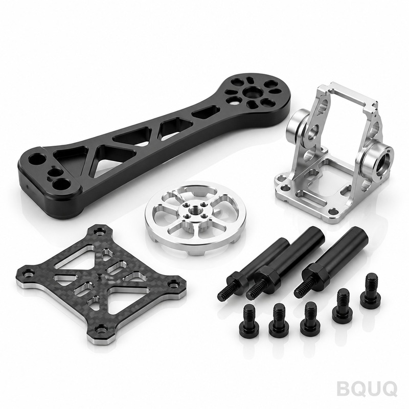
UAV Airframe Structural Bracket CNC Machining: 7075-T6, 0.8mm Wall, ±0.01mm
A UAV airframe bracket lives with a brutal contradiction: it has to be light enough to justify its own existence and stiff enough to keep a motor or a sensor aligned through every flight load and every vibration cycle. Wall thickness is where those two demands collide, and 0.8mm is close to the point where most machining processes stop behaving predictably.
Project Background & Challenge
A European UAV manufacturer builds multirotor and hybrid-electric platforms, and one recurring part group is the structural brackets that tie motor mounts, landing-gear legs and payload rails into the airframe. Volumes settle around 300 pieces a month, split across a handful of variants, with design changes driven hard by flight testing.
The material is 7075-T6 aluminum, chosen for its strength-to-weight ratio - roughly twice the yield strength of 6061-T6 - because every gram taken out of a bracket is a gram of battery or payload the aircraft can carry. But 7075-T6 punishes thin walls. It is stiffer and more brittle than 6061, far more prone to distortion when material is removed unevenly, and more sensitive to the heat of aggressive cutting.
The core feature is a 0.8mm wall running along the bracket web, with mounting hole positions held to ±0.01mm and a load-bearing interface that has to stay flat. Those two requirements fight each other. Cutting a 0.8mm wall wants gentle, symmetric machining; holding ±0.01mm hole positions wants a stable, well-clamped setup. Clamp hard and the thin web deflects; clamp light and the hole pattern drifts. On top of that, the finished bracket is hard anodized, and hard anodizing adds a brittle oxide layer that can shift fit and, if the process is sloppy, crack at sharp inner corners on a thin section.
Weight reduction means the part is designed right at the edge of what the material allows, so there is almost no margin for the usual "leave stock and machine it off" safety net. The design is what it is, and the process has to match it.
The loads are not gentle. A bracket near the motor mount sees high-frequency vibration from the rotor, and a landing-gear bracket takes a repeated impulse load on every touchdown. A 0.8mm web that measures flat on the bench but carries a hidden stress imbalance can crack in service after a few hundred flights, so "looks right" is not a useful acceptance criterion. The metallurgical state of the part matters as much as its dimensions.
BQUQ Process Solution
The strategy was to cut the bracket in stages, keep material removal symmetric, and use fixture support - not clamp pressure - to hold the thin web stable. Two things drive everything else: the sequence in which material comes off, and the way the part is supported while it does.
Staged Material Removal
Stock is reduced in several light passes instead of one heavy cut. Roughing leaves 0.4mm on the web, followed by a stress-relief pause, then semi-finishing brings the web to 0.9mm, and a final pass takes it to the 0.8mm nominal. Removing material gradually and from both faces of the web keeps the internal stress balance close to neutral, which is what prevents the classic banana-shaped warp after the clamps come off. Working from both faces also keeps the neutral axis of the web where the design placed it, rather than drifting toward whichever side was cut last.
Fixturing for the Thin Wall
Brackets are located on the stiff bosses and flange edges, never directly on the 0.8mm web. A custom soft-jaw fixture with adjustable supports sits under the web during the final passes so it cannot vibrate or deflect under load. Clamp pressure is deliberately low, and hole positions are drilled only after the web is finished and the part has relaxed, so a light spring-back cannot pull the pattern out of tolerance.
Hard Anodizing Control
Because hard anodizing builds a hard oxide layer that can crack at sharp internal corners on a thin section, every machined inner corner on the profiles is radiused before coating. Wall regions are masked where fit matters, and the machining allowance accounts for coating growth so finished fits stay inside tolerance. Parts are stress-relieved before coating, and edge protection is used in transit. Where a bracket bolts against another coated part, masking is planned so that only one of the two mating surfaces carries the full oxide layer, keeping the joint repeatable across service.
Key Specifications
| Item | Specification |
|---|---|
| Material | 7075-T6 aluminum |
| Web wall thickness | 0.8mm (thin-wall features held to ±0.02-0.05mm) |
| Mounting hole positions | ±0.01mm |
| Surface finish | Ra0.8 on mounting faces, Ra1.6 elsewhere |
| Surface treatment | Hard anodizing (black anodize also available) |
| Volume | 300 pcs/month across several variants |
| Inspection | CMM layout and wall-thickness check; CPK≥1.33 on hole positions |
| Delivery | Samples in 3-7 days, first batch in 15 days |
Quality Control & Delivery
First-article inspection covers a full CMM layout of the bracket, including wall thickness at multiple sections plus hole-position checks referenced to the mounting datum. Wall thickness on a thin web is confirmed with a contoured check fixture rather than a hand caliper, because a caliper squeezes exactly what it is measuring. Critical hole positions are gauged in-process, and CPK data ships with every batch, all under an ISO9001:2015 quality system.
Because the thin wall is the failure point, every batch also gets a sampling check of wall thickness across the web and a visual check for surface tears or chatter marks - the early warning signs of a process drifting. If a wall thickness trends toward the tolerance edge, the batch is paused and the tooling re-checked before more parts are cut.
Result: samples three to seven days after drawing release, the first 300-piece batch in 15 days, then a monthly rolling schedule. Hard-anodized parts arrive with edge protection, and any variant change is re-quoted within 48 hours.
Related Products & Resources
To see parts with the same weight and stiffness demands, browse our CNC machined drone parts in aluminum, or the CNC precision flanges & couplings line.
A closer look at a similar thin-wall structural job is in the case study on robotic joint reducer housing CNC machining. More manufacturing Q&A, including thin-wall and tolerance questions, is in our FAQ Center.
FAQ
Why machine a UAV bracket to 0.8mm walls instead of casting or 3D printing?
At 300 pieces a month, machining gives the strength of 7075-T6 with no porosity or layer-direction weakness and holds ±0.01mm on mounting holes. Casting needs tooling and rarely holds this tolerance on a thin wall, and printed parts do not yet match wrought 7075-T6 strength. Machining is the honest middle path at this volume.
Can you actually hold ±0.01mm on a 0.8mm wall?
Not on the wall thickness itself - 0.8mm features are held to ±0.02-0.05mm, which we state up front instead of promising and missing. The ±0.01mm applies to mounting hole positions and machined faces on the stiffer sections, where the setup is stable enough to guarantee it.
Will hard anodizing change my dimensions?
Yes, and we plan for it. Hard anodizing grows an oxide layer that can add roughly 0.02-0.05mm per surface, so coated fits are machined undersize to compensate. All inner corners on thin sections are radiused first to prevent cracking, and the finished part is checked again after coating.
How fast can you turn around a design change?
Samples for a revised bracket ship in three to seven days, and a first production batch of 300 pieces in 15 days. With CNC, stamping, springs and heat sinks under one roof, variant changeovers are routine. Send the updated drawing and a quotation follows within 12 hours.