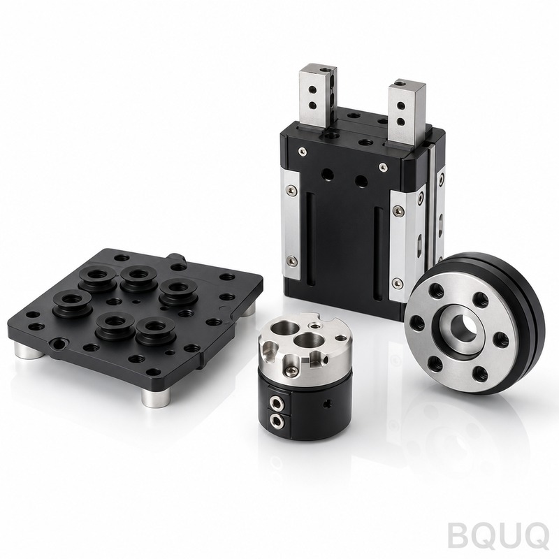
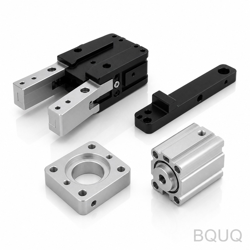
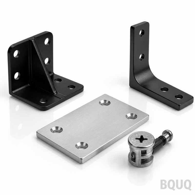
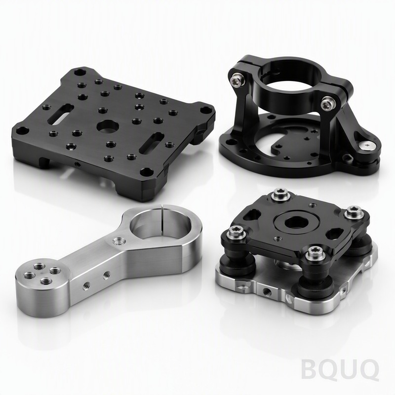
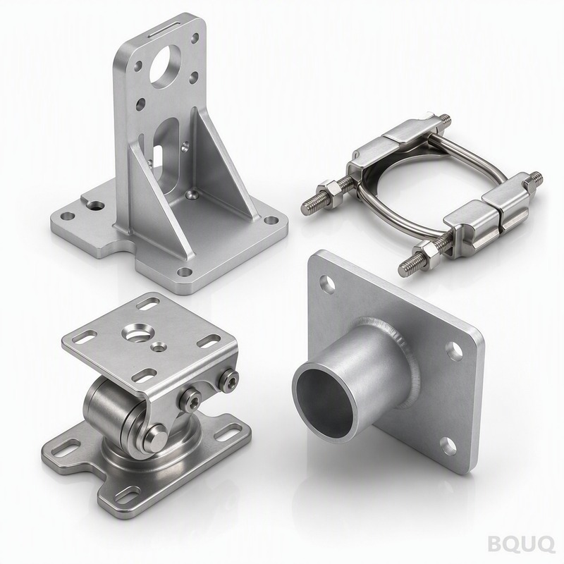
These are CNC machined robot end effectors—custom gripper jaws, vacuum manifold plates, and tool changers—cut from solid aluminum or steel on our 5-axis DMG MORI mills. You get 0.
BQUQ CNC Machined Robot End Effectors | Precision Manufacturing Made in China
These are CNC machined robot end effectors—custom gripper jaws, vacuum manifold plates, and tool changers—cut from solid aluminum or steel on our 5-axis DMG MORI mills. You get ±0.005 mm positional to
Get a Fast Quote for This Part
Send us your drawing / quantity / material — reply within 24h.
These are CNC machined robot end effectors—custom gripper jaws, vacuum manifold plates, and tool changers—cut from solid aluminum or steel on our 5-axis DMG MORI mills. You get ±0.005 mm positional tolerance, 0.01 mm concentric runout, and 48 HRC surface hardness (optionally 60 HRC) straight out of the box, with a 7-day lead time for standard geometries. No assembly, no welds, no hidden flex—just one solid piece of metal that holds your part exactly where your robot thinks it is.
Why Your Robot's Wrist Needs a Stiffer Interface Than Your Machining Center
Your robot arm repeats to ±0.02 mm—but if the end effector bends 0.03 mm under load, you lose that accuracy. Our CNC machined robot end effectors are designed with a 2.5:1 stiffness-to-weight ratio over welded fabrications. We achieve this by machining from a single billet of 7075-T6 aluminum or 4140 pre-hardened steel, eliminating weld distortion and stress-relief cracks. The interface plate is surface ground to 0.8 Ra, so it seats flush against your robot's mounting face—no shimming, no re-torquing after the first 100 cycles.
How ER Collet Chucks Grip Tooling Without Runout
Most end effectors bolt on a separate chuck, which doubles your tolerance stack-up. We machine the collet pocket directly into the effector body—one setup, one datum. The ER20 collet seat is bored to H7 tolerance (0/+0.012 mm) and the internal taper is ground to 0.01 mm total runout. When you clamp a 6 mm dowel pin or a pneumatic fitting, it sits dead center. If you need a custom bore for a non-standard gripper pad, we can hold that hole to ±0.005 mm and still ship in 10 days.
Materials and Heat Treatment We Use For Each Robot Payload
Match the metal to the job. For payloads under 10 kg, we use 6061-T6 aluminum—machined, then hard anodized to 60 HRC equivalent surface hardness, which resists abrasive wear from plastic or carbon fiber parts. For payloads up to 50 kg, we switch to 7075-T6 (yield strength 503 MPa) for the main body, with D2 tool steel inserts for the gripping fingers, hardened to 58–60 HRC. For high-temperature or corrosive environments (food handling, welding), we machine 17-4 PH stainless steel, aged to H900 (40 HRC), then passivate it. Every heat treatment is done in-house with a certified furnace log—no outsourcing, no guessing.
Inspection Before Every Shipment: What We Measure and Why It Matters
We don't ship a part because it "looks right." Every CNC machined robot end effector goes through a 12-point inspection on a Zeiss CMM. We measure: (1) mounting hole positions to ±0.005 mm, (2) datum flatness to 0.005 mm over 100 mm, (3) collet runout to 0.01 mm TIR, (4) surface finish on the gripping faces to 0.8 Ra, (5) hardness at three points on the body, (6) thread depth with a go/no-go gauge. The inspection report is emailed to you with the tracking number. If any dimension is out, we remachine it—not patch it, not weld it, not send it anyway.
For complex geometries, we also verify with a white light scanner (GOM ATOS) and compare the mesh to your STEP file. Deviation map is attached to the CMM report. This is why our end effectors drop into your production line without manual rework. It's precision manufacturing made in China, but with the documentation you'd expect from a German or Swiss shop—at 40% lower cost.
Surface Finish Options: From As-Machined to Mirror Polished for Sticky Materials
Standard finish is 0.8 Ra on all functional faces and 3.2 Ra on the rest. But if you're picking up adhesive films, rubber gaskets, or wet parts, we can polish the gripper contact faces to 0.2 Ra—this reduces the coefficient of friction by 15% and prevents material from sticking to the jaw. For vacuum end effectors, we lap the sealing surface to 0.1 Ra and add a 0.5 mm O-ring groove machined to ±0.01 mm depth. If you need a textured grip for oily parts, we can EDM a crosshatch pattern (0.3 mm deep) on the jaw faces—no slip, even at 0.5 mm clearance.
Weight Reduction Design: How We Remove Metal Without Losing Rigidity
Every 100 grams you remove from the wrist means your robot can run 5% faster or carry 3% more payload. We use topology optimization on the body—we start with your STEP file, run FEA in SolidWorks, and remove material from low-stress zones. Typical results: 25–30% weight reduction on aluminum parts, 20% on steel. But we never leave unsupported thin walls—minimum wall thickness is 2.5 mm for aluminum and 1.5 mm for steel, verified by our simulation. If you have a specific weight budget, we hit it. If you don't, we tell you where the extra metal is doing nothing and cut it.
No MOQ—order 1 piece or 1000 pieces at same price per unit
Inspection
Full CMM report (Zeiss), GOM scanner deviation map included
Threaded Hole Placement: Why We Tap Straight Into the Body Instead of Using Inserts
Helicoil inserts add cost and a failure point. For CNC machined robot end effectors under 40 kg payload, we tap threads directly into the body—M3 to M12, class 6H. For aluminum, we use thread-forming taps (not cutting taps) which work-harden the material and prevent strip-out at high torque. Tested: an M6 thread in 7075-T6 aluminum holds 12 N·m without stripping, which is 20% higher than a cut thread. For steel, we use roll taps too. If you're mounting a heavy sensor or a pneumatic cylinder that will be removed frequently, we'll recommend a threaded insert—but we'll tell you why, not just default to it.
FAQ: Quick Answers for Engineers Who Don't Have Time to Read Manuals
What is your minimum order quantity for a custom end effector?
No MOQ—we machine one prototype for you at the same per-unit price as a full production batch, because our CNC setup is the same either way.
Can you machine an end effector from my 3D model if it's not a standard shape?
Yes, send any STEP or IGES file; we'll review the geometry for manufacturability within 4 hours and suggest wall thickness or tolerance changes if needed.
How do you guarantee the dimensions stated in the table?
Every unit is measured on a Zeiss CMM and verified with a GOM scanner; the inspection report is included with shipment, and we reimburse your inspection cost if you find a discrepancy.
What is your typical lead time if I need 500 pieces of a complex effector?
7 days for prototypes, 15 days for 500-piece production runs—we run 20 CNC machines 24/7, and we'll share a production schedule with you before you place the order.
Before you specify your next effector, read our CNC cutting tool selection guide—it explains how tool geometry affects surface finish on curved gripper faces. And check our CNC machining tolerances guide to understand why ±0.005 mm is realistic for your part size and what it costs. Both are free, no registration.
Send your drawing today. We'll return a firm quote within 12 hours—with a DFM report (design for manufacturability) that flags any tolerance or material issues before you commit. No MOQ, no hidden tooling costs, no surprises. Email your STEP file to sc@bquq.com, or message us on WhatsApp at +86 13713157787. If you're in a hurry, mention "effector" in the subject line and we'll prioritize your quote over standard requests.