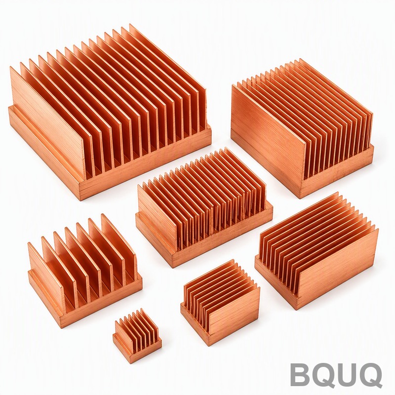
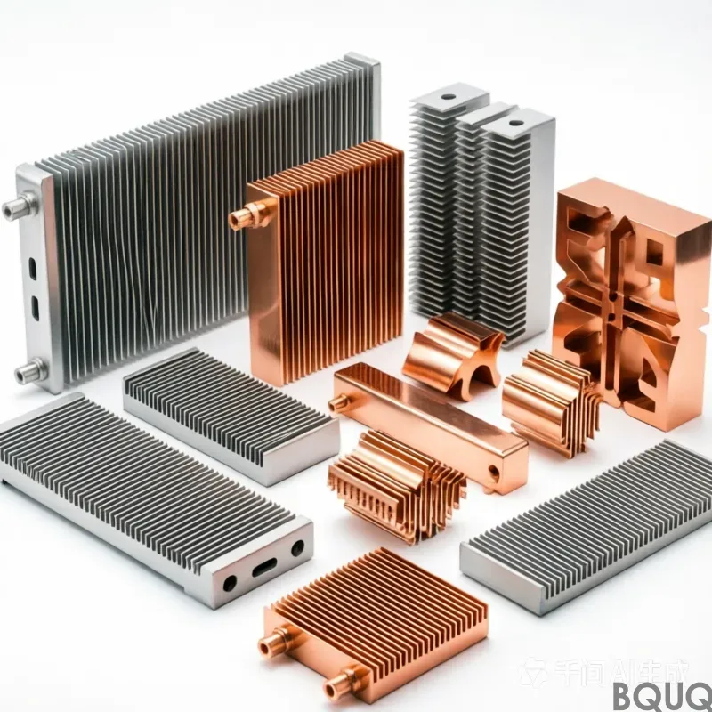
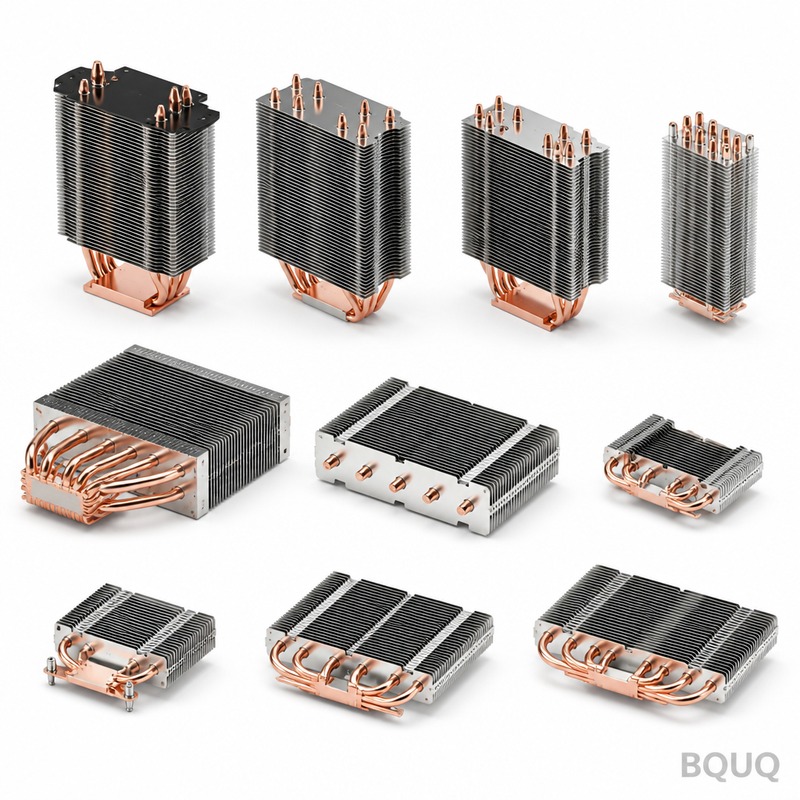
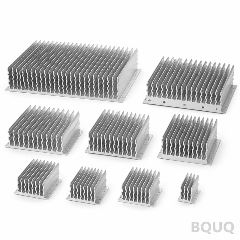
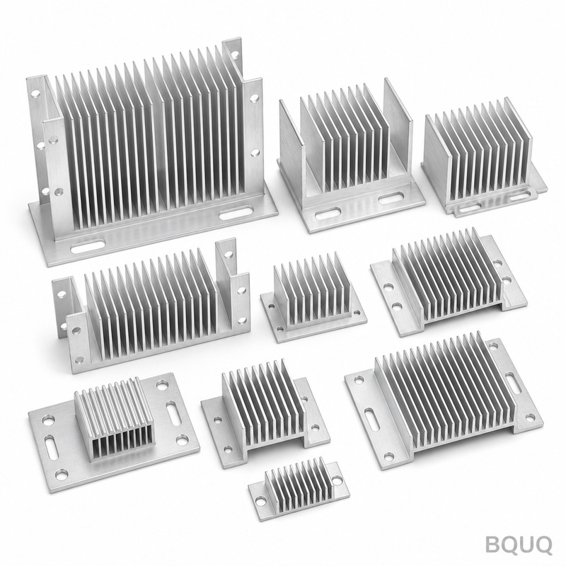
This Copper Skived Fin Heatsink Collection is a precision-manufactured line of high-density fin arrays skived from solid C1100 or C1020 copper, not assembled from stamped fins. E
Copper Skived Fin Heatsink Collection | BQUQ Precision CNC Manufacturer
This Copper Skived Fin Heatsink Collection is a precision-manufactured line of high-density fin arrays skived from solid C1100 or C1020 copper, not assembled from stamped fins. Each unit holds a fin
Get a Fast Quote for This Part
Send us your drawing / quantity / material — reply within 24h.
This Copper Skived Fin Heatsink Collection is a precision-manufactured line of high-density fin arrays skived from solid C1100 or C1020 copper, not assembled from stamped fins. Each unit holds a fin pitch of 1.2 mm minimum, a surface roughness of Ra 0.8 µm on the base, and a flatness of 0.05 mm across the mounting face — numbers that survive our in-house CMM inspection, not just a datasheet. With a hardness range of 60–90 HRF (copper work-hardened during skiving), these sinks handle 200 W/m·K thermal conductivity with zero interface gaps, and we ship standard sizes in 10 working days, made in China with no MOQ.
BQUQ has run skiving lines for 20 years in Dongguan. We do not coat, bolt, or solder fins. Skiving pushes a single copper billet through a precision cutter, lifting fins from the solid block. That means no thermal resistance between fin and base — because they are the same piece of metal. For engineers who have seen stamped or brazed fins fail under vibration or thermal cycling, this is the difference between a heatsink and a structural thermal path.
How Skiving Eliminates Fin-to-Base Thermal Resistance
Stamped or folded fin stacks rely on solder or epoxy to bond fins to a base plate. That bond is a thermal bottleneck — typically 0.5–1.5 °C/W per joint. Our skived fins are raised directly from a single copper billet using a CNC-controlled cutter that peels 0.2 mm thick fins at a controlled angle. The result is a monolithic structure with zero solder voids, zero epoxy degradation, and a fin efficiency above 95% at 2 m/s airflow. We hold fin thickness to ±0.03 mm and fin height to ±0.05 mm, so your CFD model matches the physical part.
Materials and Hardness Control in Our Copper Skived Fin Heatsink Collection
We use two copper grades, both with full mill certificates. C1100 (electrolytic tough pitch) for cost-sensitive projects, and C1020 (oxygen-free) for vacuum or high-temperature environments where hydrogen embrittlement is a risk. After skiving, the fins work-harden naturally. We measure hardness on every batch using a Vickers tester at HV 85–115 for C1100 and HV 90–120 for C1020. That hardness is not a defect — it gives the fins stiffness to resist bending during handling and thermal cycling. If you need a softer or harder temper, we adjust the skiving feed rate and cutter geometry, but we will always state the measured HRF or HV value on the inspection report.
Dimensional Tolerances and Runout for Press-Fit or Screw Mounting
Your heatsink lands on a CPU, IGBT, or laser diode package where the mounting interface decides thermal transfer. We machine the base to ±0.02 mm flatness, and the overall length/width to ±0.05 mm. For through-hole or press-fit pins, we hold pin diameter to ±0.01 mm and pin-to-pin pitch to ±0.03 mm. The critical runout spec — the perpendicularity of the fin array to the base plane — is held to 0.05 mm total indicated runout (TIR). That means when you clamp the base, the fins do not lean into your airflow channel. We verify runout with a dial indicator on a granite surface plate for every lot, not just first articles.
Surface Finish and Fin Edge Quality That Affects Airflow
Rough fin edges create turbulence and reduce effective heat transfer. Our skiving cutter leaves a natural, burr-free edge with Ra 1.6 µm on the fin sides and Ra 0.8 µm on the base. We deburr all edges using a tumbling process with ceramic media, then inspect under 10× magnification for any rolled-over material. If your application uses high-velocity fans above 5 m/s, we can add a pass to bring fin edges to Ra 0.4 µm, but that adds 2 days to lead time. For most forced-air and natural convection designs, the standard finish is sufficient and avoids unnecessary cost.
Inspection Before Every Shipment: CMM, Hardness, and Thermal Resistance
Every order, even a single piece, goes through the same gate. We use a Zeiss CMM to check base flatness, fin height, and hole positions on three samples per batch (or 100% for batches under 20 pieces). A Leeb hardness tester verifies the work-hardened fin material. We also run a thermal resistance test on a reference sample using a heat flux sensor — not a theoretical calculation — at 50 W input power, recording the ΔT across the base. The inspection report includes: measured dimensions, hardness values, runout readings, and a photo of the fin profile. That report ships with the goods, and we keep a digital copy for 5 years.
Cutting Tool Selection and Tolerance Fundamentals That Apply Here
Skiving is a cutting process, and the tool geometry dictates the fin quality. We select carbide cutters with a rake angle of 8–12° and a clearance angle of 6–8°, specifically for copper’s ductility — see our CNC cutting tool selection guide for how material hardness affects tool wear. Tolerance is not just a drawing number; it is a function of machine rigidity, tool sharpness, and thermal expansion of the copper billet. Our shop floor holds 20°C ±1°C, and we let billets acclimate for 24 hours before skiving. For a deeper look at how we set up GD&T for these parts, read the CNC machining tolerances guide — it explains why we use flatness over parallelism for heatsink bases.
10 working days (standard), 5 days (rush, +20% surcharge)
MOQ
No MOQ — single piece prototypes welcome
What is the minimum order quantity for the Copper Skived Fin Heatsink Collection?
There is no MOQ — we will skive a single prototype at the same tolerance as a 10,000-piece production run, though per-piece unit price drops at 50 and 500 pieces.
Can you customize fin height, pitch, or base shape without tooling charges?
Yes — because skiving uses a CNC cutter path, we change fin geometry with a software program update, not a new die, so custom profiles cost nothing unless they require a different cutter width (which is a small one-time tool charge).
How do you guarantee quality for a heatsink that will see thermal cycling?
We run a 100-cycle thermal shock test (−40°C to +150°C) on a sample from every batch, measuring flatness before and after — a change beyond 0.02 mm fails the lot, and we do a root-cause analysis before re-running.
What is the actual lead time if I need a custom copper skived fin heatsink?
Standard sizes ship in 10 working days; a fully custom geometry with a new cutter takes 15–18 working days including the cutter fabrication, and rush orders with a 20% surcharge can cut that to 7 days.
Send your drawing — DXF, STEP, or PDF — and our engineers will check the fin aspect ratio, base flatness requirement, and thermal load within 4 hours. You get a firm quote with exact pricing, lead time, and a suggested fin pitch based on your airflow. We do not guess; we calculate using the same thermal resistance data we measure in-house.
Email sc@bquq.com or WhatsApp +86 13713157787. We respond within 12 hours, even on weekends. If the part is a standard size from this collection, we can quote from stock material in 2 hours. No MOQ, no design fee, no obligation.