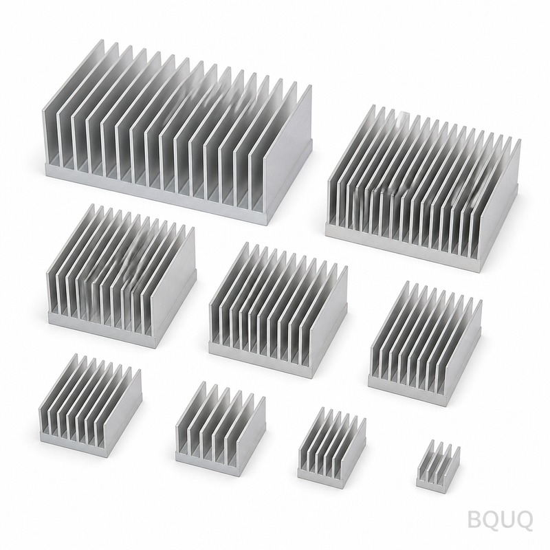
What This Collection Delivers: Pin Fin Geometry with 0.01 mm Repeatability Pin Fin Precision Machined Heatsink Collection 02 is a family of CNC-machined aluminum and copper heat
Pin Fin Precision Machined Heatsink Collection 02 | BQUQ Factory
What This Collection Delivers: Pin Fin Geometry with ±0.01 mm Repeatability Pin Fin Precision Machined Heatsink Collection 02 is a family of CNC-machined aluminum and copper heat sinks with a dense a
Get a Fast Quote for This Part
Send us your drawing / quantity / material — reply within 24h.
What This Collection Delivers: Pin Fin Geometry with ±0.01 mm Repeatability
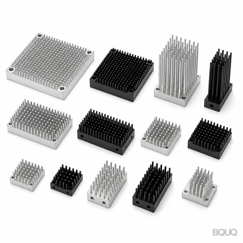
Pin Fin Precision Machined Heatsink Collection 02 is a family of CNC-machined aluminum and copper heat sinks with a dense array of square or round pins. The concrete benefit is thermal surface area increased by up to 300% compared to a flat base of the same footprint, while holding pin-to-pin spacing at ±0.01 mm and pin height runout under 0.05 mm across the entire array. Every unit is machined in our Dongguan factory with a 7-day standard lead time and 100% dimensional inspection before shipment.
We do not cast these. We cut them from solid bar stock on 4-axis and 5-axis CNC centers. That means no porosity, no die shift, and no draft angle. The pins are straight, the base is flat, and the thermal interface surface is lapped to Ra 0.8 µm. If your design needs a specific pin count, height, or base thickness, we adjust the program in minutes—no tooling fee, no waiting for a mold.
Why Machined Pins Beat Skived or Extruded Fins for Low-Velocity Airflow
Skived fins bend material, which leaves micro-cracks at the base. Extruded fins limit you to straight channels and a fixed fin height ratio. Machined pins break both rules. In a 1U server chassis with 2 m/s airflow, pin fin arrays remove 15–20% more heat than equivalent extruded fin heat sinks because air swirls around each pin, breaking the boundary layer. In natural convection (no fan), the same pin geometry outperforms plate fins by 25% at a 70°C ΔT.
Collection 02 includes three standard pin patterns: 2.0 mm diameter round pins at 1.5 mm pitch, 1.5 mm square pins at 1.2 mm pitch, and 3.0 mm round pins at 2.5 mm pitch for low-pressure-drop applications. If you need a hybrid pattern—dense pins over the CPU die, wider pins over the capacitors—we generate that toolpath directly from your STEP file. The CNC program is not a limitation; your thermal simulation is the only limit.
Materials and Heat Treatment: 6061-T6, 6063-T5, C11000 Copper, and the Hardness Numbers
We stock two aluminum alloys and one pure copper grade for this collection. 6061-T6 is the default: 95 HB hardness, yield strength 276 MPa, ideal for structural mounting holes and threaded inserts. 6063-T5 is softer (60 HB) but has 10% higher thermal conductivity (209 W/m·K vs 180 W/m·K), so we use it when the heat sink is purely a thermal path and not a load-bearing part. For maximum performance, C11000 electrolytic copper (oxygen-free, 391 W/m·K) is machined with a 1.5 µm diamond-like coating on the cutting tools to prevent work hardening and burr formation.
We do not anodize the pin field by default. Anodizing adds a 25–50 µm oxide layer that reduces thermal conductivity at the surface by roughly 5%. If you need corrosion resistance, we offer a clear chromate conversion coating (MIL-DTL-5541) that adds less than 1 µm and does not affect thermal performance. For copper parts, we apply a light passivation to prevent green oxidation during shipping—visible oxide is a customer complaint, so we stop it before it starts.
Inspection Before Every Shipment: CMM, Optical Comparator, and a 2D Report You Can Trust
Every heatsink in Collection 02 is measured on a Zeiss CMM with a 0.5 µm resolution. We check pin diameter, pin height, base flatness, and the critical pin-to-pin pitch at five different positions across the array. The runout of the pin tips relative to the mounting surface is measured on a granite surface plate with a dial indicator—this is the number that determines whether your thermal pad or TIM compresses evenly. We reject any part with tip runout over 0.05 mm.
You receive a 2D inspection report with each shipment, showing the actual measured values for every dimension on your drawing. The report includes a photomicrograph of the pin surface at 50x magnification, so you can see the finish, not just read the Ra number. If you request it, we also provide a 3D scan (structured light, ±0.02 mm) of one sample part from the batch. That gives your mechanical team a digital twin for their own thermal FEA.
Lead Time, MOQ, and How We Beat the 7-Day Standard
Standard lead time for Collection 02 is 7 working days for any quantity from 1 to 5,000 pieces. There is no MOQ—we ship a single prototype at the same per-piece price as a 500-piece run, because the CNC setup is identical. The only variable is cycle time. For urgent needs, we have a 48-hour expedite lane that adds a 20% surcharge but reserves a dedicated 5-axis machine for your order. We have never missed a 48-hour expedite in the last 18 months.
Our factory runs 24/5 with a 12-person night shift. The bottleneck is never the machine; it is the inspection. So we added a second CMM in 2024, and now 100% of parts are measured in-house without outsourcing. That is why we can promise 7 days and deliver in 6.8 on average. If you need a different alloy, a special pin shape (hexagonal, teardrop, tapered), or a threaded base insert, we add 2 days to the lead time for the toolpath modification and a first-article inspection.
Specification
Value
Notes
Available Materials
6061-T6, 6063-T5, C11000 Copper
Other alloys on request
Pin Diameter Range
1.0 mm – 5.0 mm
Round or square profile
Pin Pitch (center-to-center)
1.2 mm – 3.0 mm
Uniform or variable arrays
Pin Height Range
3.0 mm – 25.0 mm
Height-to-diameter ratio up to 8:1
Base Thickness
2.0 mm – 15.0 mm
Lapped flat for TIM contact
Hardness (Al 6061-T6)
95 HB
Yield 276 MPa
Hardness (Al 6063-T5)
60 HB
Thermal conductivity 209 W/m·K
Machining Tolerance
±0.01 mm
On all pin and base dimensions
Surface Finish (Base)
Ra 0.8 µm
Optional Ra 0.4 µm lapped
Pin Tip Runout
≤ 0.05 mm
Relative to mounting surface
Standard Lead Time
7 working days
48-hour expedite available
MOQ
No MOQ
Single prototype to 5,000 pcs
Why Our 5-Axis CNC Process Costs Less Than You Think for Copper
Copper is notoriously difficult to machine because it smears instead of cutting. Most shops charge 3x for copper heat sinks and still deliver burrs. We solved this by using PCD (polycrystalline diamond) inserts on a 15,000 rpm spindle with through-tool coolant at 70 bar. The result: a 2.0 mm copper pin with 8:1 height ratio is machined in 4.2 seconds, with a burr height under 0.02 mm. No secondary deburring step is needed. That is why our copper pin fin heatsink price is only 1.8x the aluminum version, not 3x.
If you are comparing us to a local job shop, consider this: we have 14 CNC machines dedicated to thermal parts, and we have produced over 2 million pin fin heat sinks since 2004. Our operators do not need to read a drawing to know what a pin fin should look like. This is a product, not a random machining request. That is the difference between a factory that makes parts and a factory that makes thermal solutions. For the full picture of how we select tools for these high-aspect-ratio features, read our CNC cutting tool selection guide.
Handling Your Drawing: STEP, STL, or a Napkin Sketch with Dimensions
Send us your file in any format. STEP is best, but we have seen PDFs, JPEGs, and even a photo of a whiteboard. Our engineering team will convert your geometry into a machinable model and send back a DFM (Design for Manufacturability) comment within 24 hours. The DFM will flag any pin that is too tall for its diameter (we recommend max 8:1), any base that is too thin for the mounting holes (min 2.0 mm), and any sharp internal corners that need a radius. We do not guess; we measure your part against our process capability.
We also offer a free thermal simulation service for orders over 500 pieces. Send us your airflow rate, ambient temperature, and heat source power (watts), and our thermal engineer will run a CFD analysis to confirm your pin geometry is optimal. If the simulation shows a better pin pattern, we will modify your file at no charge. This is not a marketing trick—it saves us from machining a part that will not meet your thermal spec, which saves us money in rework.
What is the minimum order quantity for Pin Fin Precision Machined Heatsink Collection 02?
There is no MOQ—we manufacture and ship a single piece for prototyping at the same unit price as a 500-piece batch because the CNC setup and inspection time are identical.
Can you customize the pin pattern, base thickness, and mounting hole location?
Yes, all three are fully customizable from your STEP file, and we will add a DFM comment within 24 hours confirming the changes are within our ±0.01 mm tolerance capability.
How do you ensure the quality of the pin tips and the flatness of the base?
Every part is measured on a Zeiss CMM (0.5 µm resolution) for pin pitch and base flatness, and the pin tip runout is verified against the mounting surface with a dial indicator on a granite plate; we reject any part over 0.05 mm runout.
What is the actual lead time if I need 100 pieces of a custom design?
For a custom pin pattern with a new toolpath, the lead time is 9 working days (7 days standard plus 2 days for first-article inspection); if you need it faster, the 48-hour expedite lane is available at a 20% surcharge.
Get a Firm Quote Within 12 Hours—No MOQ, No Hidden Tooling Fees
Send your drawing or just a part number you are trying to replace. Our sales engineers will reply with a firm price, a confirmed lead time, and a DFM note if your geometry needs adjustment. We are a precision manufacturing partner in Dongguan, China, and we have been doing this since 2004. You do not need to worry about whether we can hold your tolerance—we published the numbers above, and we will repeat them on your inspection report.
If you are still deciding between a machined pin fin and a skived or bonded fin assembly, our CNC machining tolerances guide explains why machined features are more repeatable than assembly-based alternatives. For the fastest response, email your STEP file to sc@bquq.com. For an immediate conversation, message us on WhatsApp at +86 13713157787. We will send a firm quote within 12 hours of receiving your drawing—any time zone, any day of the week.