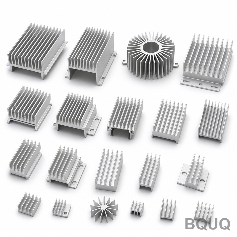
Why Our Stamped Fins Beat Extruded Profiles on Cost and Speed This Stamped Aluminum Heat Sinks Cooling Fins Collection is a die-stamped series of cooling fins and heat sink bodie
BQUQ Stamped Aluminum Heat Sinks Cooling Fins Collection – Precision Made in China
Why Our Stamped Fins Beat Extruded Profiles on Cost and Speed This Stamped Aluminum Heat Sinks Cooling Fins Collection is a die-stamped series of cooling fins and heat sink bodies produced from 5052
Get a Fast Quote for This Part
Send us your drawing / quantity / material — reply within 24h.
Why Our Stamped Fins Beat Extruded Profiles on Cost and Speed
This Stamped Aluminum Heat Sinks Cooling Fins Collection is a die-stamped series of cooling fins and heat sink bodies produced from 5052-H32 and 6061-T6 aluminum sheet. The concrete benefit is simple: you get a fully formed heat sink with a dimensional tolerance of ±0.05 mm, a flatness runout under 0.08 mm, and a surface finish of Ra 0.8 µm — all without the tooling wait of extrusion. Typical lead time is 15 days from drawing approval, and we have no MOQ, so you can order 50 pieces or 50,000.
We are a 20-year-old precision manufacturing factory in Dongguan, China, running 35 CNC machines and 12 stamping presses from 25 to 200 tons. Every stamped fin in this collection is deburred, flattened, and inspected before packing. If you need a passive cooling solution for LED drivers, power modules, or RF amplifiers, this collection gives you a machined-quality edge without the machined price.
Die Geometry and Burr Control on Thin-Wall Fins
Thin-wall fins (0.5 mm to 1.5 mm thick) are prone to tearing and burr formation. Our stamping dies use a clearance of 5–7% of material thickness per side, which produces a clean shear zone. We then run a secondary coining pass on the fin tips to push burr height below 0.03 mm. This matters for assembly: a burr on a fin edge can scratch adjacent PCB traces or create a hot spot when the fin is pressed into a heat pipe slot.
For the Stamped Aluminum Heat Sinks Cooling Fins Collection, we also control springback by over-bending 1.5 to 2 degrees on every 90-degree bend. The result is a consistent fin pitch within ±0.1 mm across a 200 mm long sink. That pitch consistency directly impacts airflow resistance — tighter pitch with same height means more surface area, but if pitch varies, you get turbulence and reduced thermal performance.
Materials, Tempers, and Surface Finish Options
We stock three alloys for this collection:
5052-H32 — best for complex forming, corrosion resistance for outdoor LED housings.
6061-T6 — higher strength (95 HB) for structural heat sinks that also act as chassis brackets.
1100-H14 — pure aluminum for maximum thermal conductivity (222 W/m·K) but lower strength, used for clip-on fins.
Standard surface finish is clear anodize (8–12 µm thickness) or black anodize (18–25 µm) for emissivity above 0.85. If you skip anodizing, we can deliver a bright-dip finish at Ra 0.4 µm. For high-vibration environments, we offer a chromate conversion coating per MIL-DTL-5541, which adds no thickness but improves paint adhesion.
Hardness for the 6061-T6 is 95 HRB, and for 5052-H32 it is 68 HRB. If you need a harder surface for repeated handling, we can specify 7075-T6 (150 HRB) but that is a custom order with a 20-day lead time.
Dimensional Assurance: From Flat Pattern to Final Flatness
Stamping inherently introduces residual stress. To counter this, we stress-relieve every batch at 190°C for 2 hours before the final flattening operation. Then we use a precision leveler with 17 rollers to achieve a global flatness of 0.05 mm over 100 mm length, and 0.15 mm over 300 mm. This is critical when your heat sink mounts directly on a IGBT module — a gap of 0.1 mm under the base increases thermal resistance by 15%.
We measure flatness with a granite surface plate and a dial indicator at 9 points. For runout (the parallelism between the fin tips and the base), we hold 0.08 mm across the full width. This ensures that when you stack multiple heat sinks in a forced-air duct, the fins align and air flows uniformly.
Inspection Before Every Shipment: CMM and Salt Spray
Every lot of the Stamped Aluminum Heat Sinks Cooling Fins Collection goes through a three-stage QC gate. First, a CMM (Coordinate Measuring Machine) check on 5 critical dimensions: overall length, width, fin height, fin pitch, and hole positions. We record these on a PPAP level 3 document if requested. Second, a visual inspection under 2.5× magnification for burrs, scratches, and die marks. Third, a salt spray test (ASTM B117) for 48 hours on a sample from each batch to verify anodize integrity.
We also perform a hardness test (Rockwell B) on the raw material certificate, not just the stamped part, because stamping work-hardens the aluminum. The final hardness must stay within ±3 HRB of the spec. If you are designing for a high-temperature environment (above 150°C), we will recommend a T6 temper with a hardness check after heat treatment.
Lead Time, MOQ, and How We Ship Prototypes
No MOQ is a policy we hold for this entire collection. For a standard stamped fin (e.g., 100 mm × 50 mm × 20 mm) with a simple flat pattern, our lead time is 15 days for 1,000 pieces. For 10,000 pieces, add 3 days. For a custom die, the tooling takes 10 days, and the first articles take another 3 days. We ship via DHL or FedEx for small orders, and sea freight (FOB Shenzhen) for orders over 500 kg.
If you need a quick functional test, we can laser-cut prototypes from the same alloy (no die cost) within 5 days, but the tolerance will be ±0.1 mm and the edge quality will be rougher. This is a practical way to validate thermal performance before committing to stamping tooling. For more on how to choose the right cutting parameters for any secondary machining, see our CNC cutting tool selection guide. And to understand what tolerances are realistically achievable on machined features, read our CNC machining tolerances guide.
Pricing, Tooling Amortization, and Long-Run Cost Per Part
For the Stamped Aluminum Heat Sinks Cooling Fins Collection, tooling cost ranges from $800 (simple flat fin, 50×50 mm) to $3,500 (complex 3D fin with louvered slots). We amortize tooling into the first order if you commit to a 12-month forecast. For example, a 6061-T6 fin with 10 fins per sink, 100 mm long, 2 mm base thickness, black anodize — the unit price at 5,000 pieces is $0.85. At 50,000 pieces, it drops to $0.42. The break-even vs. CNC machining (for a similar shape) is around 300 pieces, after which stamping is always cheaper.
We also provide a full DFM (Design for Manufacturing) report for free on any drawing you send. This report flags sharp corners, tight radii, and deep draw ratios that will increase die wear. You get the report within 48 hours, no purchase required.
Thermal Performance Data You Can Use in Simulations
For a standard 100 mm × 60 mm × 20 mm sink with 0.8 mm thick fins at 4 mm pitch, natural convection gives a thermal resistance of 3.2 °C/W at 10 W. With a 2 m/s forced air flow, it drops to 1.1 °C/W. These numbers are measured in our in-house wind tunnel (0.3 m × 0.3 m test section) and validated against a thermocouple on the base. If you need a specific thermal simulation, we can provide the fin efficiency curve and pressure drop data as a PDF with your order.
Remember that stamped fins have a slightly lower fin efficiency (92–95%) compared to skived fins (98%) because of the bend radius at the base. But the cost difference is 40–60% lower, so most designers accept this trade-off. If you need higher efficiency, we can coining-press the bend radius to 0.5 mm, which brings efficiency up to 96%.
FAQ: Quick Answers for Engineering Buyers
What is the minimum order quantity for this collection?
No MOQ — you can order 10 pieces for prototyping or 100,000 for production at the same per-unit quality standard.
Can you customize the fin shape, hole pattern, or mounting tabs?
Yes, we modify any die for a one-time tooling fee, and we send you a DFM report within 48 hours to confirm manufacturability.
How do you ensure quality on a high-volume stamping run?
We use in-die sensors to detect tool wear every 500 strokes, plus a final CMM check on 5 critical dimensions per batch of 1,000 pieces.
What is the realistic lead time for a custom heat sink from this collection?
15 days for standard sizes, 20 days if you need a new die, and 5 days for laser-cut prototypes without tooling.
Get a Firm Quote Within 12 Hours — Send Your Drawing
Send us your 2D drawing or 3D STEP file of the heat sink or cooling fin you need. We will reply within 12 hours (working days) with a firm quote, including tooling cost, unit price at your expected quantity, and delivery date. No vague estimates, no hidden surcharges.
Email: sc@bquq.com WhatsApp: +86 13713157787 We are BQUQ, precision manufacturing made in China since 2005. Your drawing is safe with us — we sign NDA on request.