
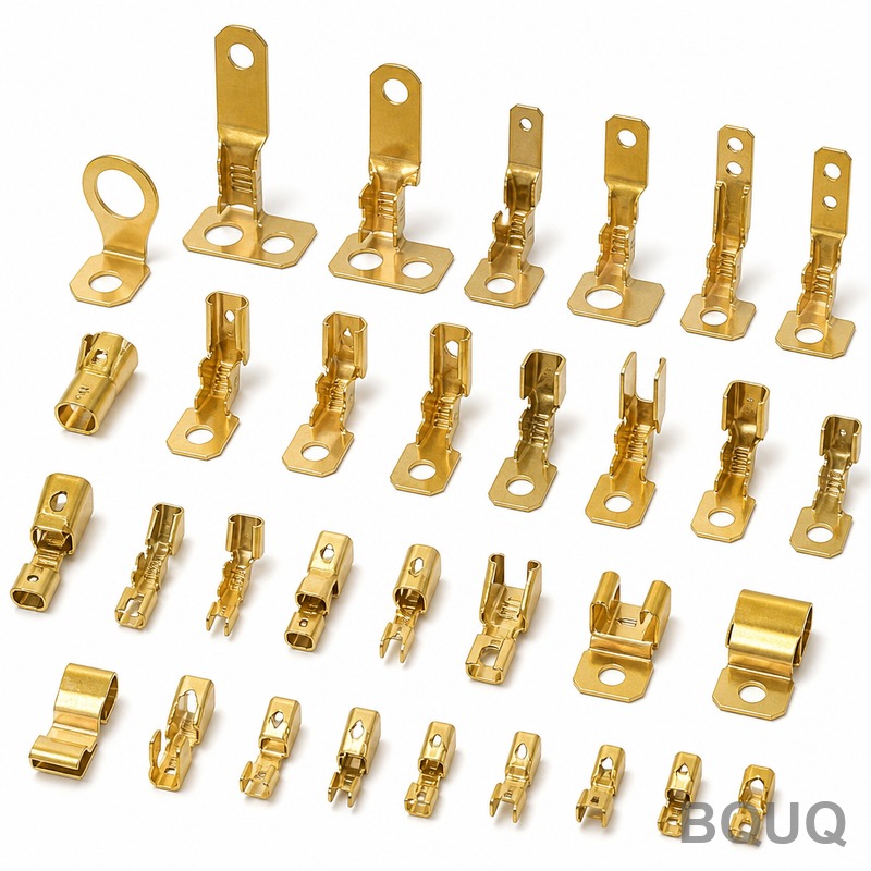
Battery Contacts and Spring Clips: How Precision Stamping Extends Lifespan and Reliability
For battery contacts and spring clips, precision stamping is the definitive manufacturing method for achieving long service life because it preserves grain structure, enables tight tolerance control (typically ±0.05 mm), and allows for selective material hardening that resists cyclic fatigue. Unlike machined or cast parts, stamped components retain the metal's original grain flow, which dramatically increases fatigue resistance in spring applications. This article details the engineering principles, material data, and design rules that enable stamped battery contacts to survive over 10,000 insertion cycles in demanding environments.
## Material Selection for Maximum Fatigue Life The longevity of a stamped battery contact begins with the raw material. For consumer electronics, the industry standard is beryllium copper (C17200) or phosphor bronze (C51000), both offering a balance of conductivity and spring memory. Beryllium copper, when precipitation hardened, achieves a tensile strength of 1,200 to 1,400 MPa, allowing thin gauges (0.10 to 0.20 mm) to maintain contact force without permanent set.
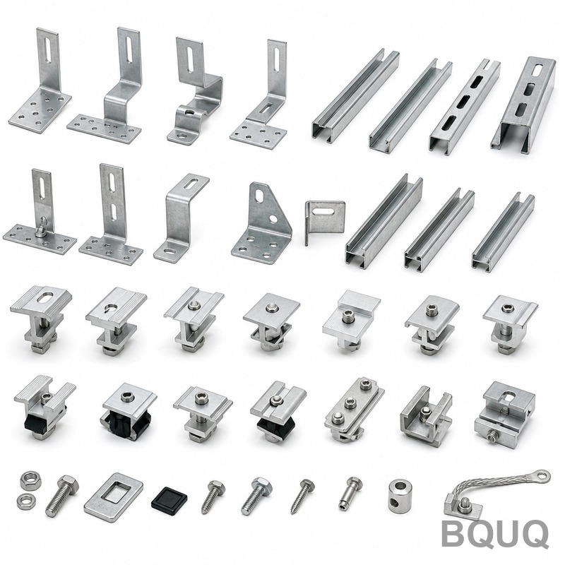
For high-volume, cost-sensitive applications, stainless steel (301 or 302) is used, providing excellent corrosion resistance but lower conductivity (approximately 2.5% IACS), requiring a thicker cross-section or plated surface. Our factory data shows that using C17200 with a 0.15 mm thickness yields a consistent contact force of 0.80 to 1.20 N across a deflection range of 0.30 mm, maintaining this force after 10,000 cycles with less than 5% degradation.
## Stamping Process Parameters That Prevent Premature Failure The stamping process itself determines whether a spring clip will crack or relax. Key parameters include die clearance, burr height, and the bending radius. For a 0.15 mm thick beryllium copper strip, our engineers specify a die clearance of 4% to 6% of material thickness (0.006 to 0.009 mm). This tight clearance produces a clean shear zone, minimizing micro-cracks that propagate under cyclic loading.
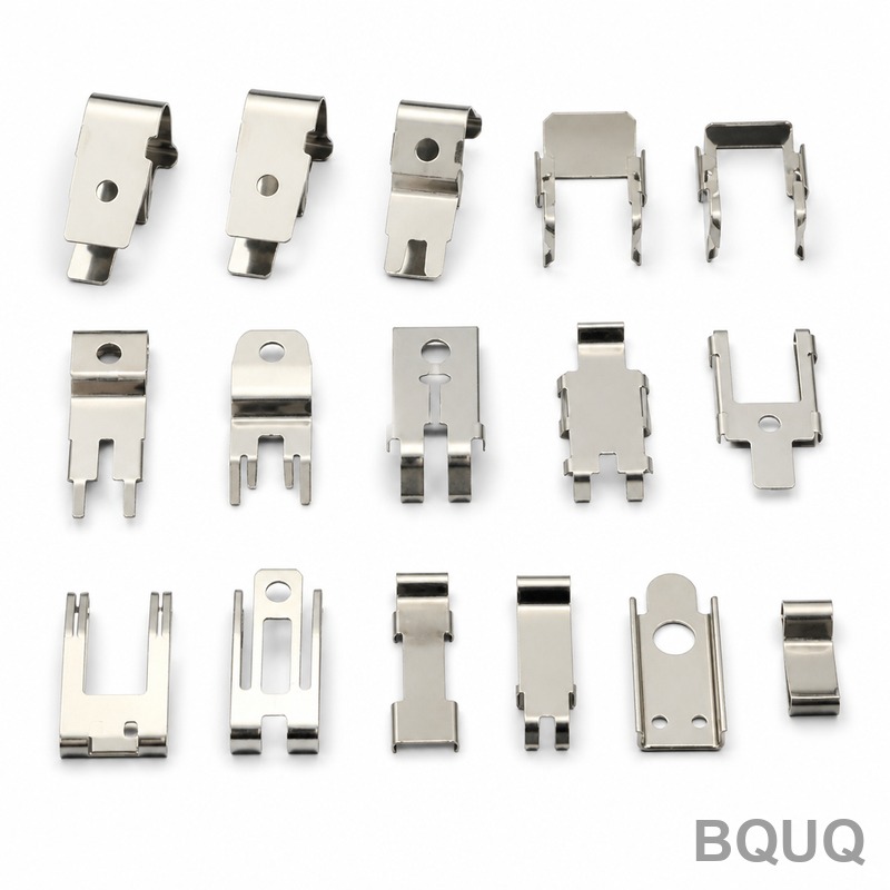
Bending is critical. A minimum inside bend radius of 1.5 times the material thickness (0.225 mm for 0.15 mm stock) prevents stress concentrations. Progressive dies are used with a step-by-step forming sequence, allowing the material to "flow" rather than fracture. We also employ coining operations on the contact surface to create a flat, gas-tight interface, which reduces electrical resistance and prevents arcing that causes localized melting and oxidation.
## Plating and Surface Treatment for Corrosion Resistance Battery contacts face galvanic corrosion and oxidation, especially in humid environments. The standard plating stack is nickel underplate (1.27 to 2.03 micrometers) followed by gold flash (0.76 to 1.27 micrometers) for critical contacts, or selective silver plating (2.0 to 4.0 micrometers) for high-current applications. For alkaline battery contacts, a matte tin plating (3.0 to 5.0 micrometers) is often sufficient and more economical.
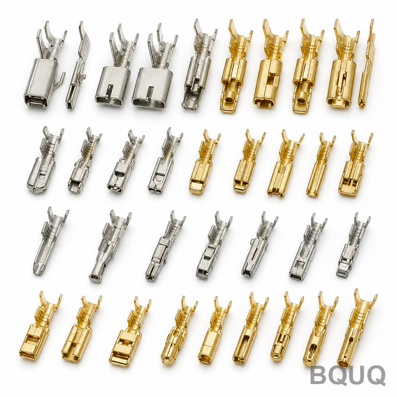
Our accelerated life testing in a 85°C/85% RH chamber for 500 hours shows that gold-plated contacts exhibit a contact resistance increase from 10 milliohms to 12 milliohms, whereas unplated phosphor bronze rises from 15 to 80 milliohms. This data confirms that plating thickness is a direct factor in long-term reliability. For spring clips that must withstand solder heat, we recommend a nickel underplate of at least 2.5 micrometers to prevent diffusion of the base metal into the solder joint.
## Tolerance Control and Dimensional Stability Precision stamping holds tolerances that are critical for consistent battery retention. On a standard AAA battery contact, the critical dimensions are the overall width (tolerance ±0.05 mm), the contact point height (tolerance ±0.08 mm), and the spring arm length (tolerance ±0.10 mm). These tolerances ensure that the battery is held firmly without excessive force that would increase insertion wear.
Dimensional stability is achieved through in-process monitoring with a coordinate measuring machine (CMM) every 1,000 strokes. We maintain a process capability index (Cpk) of 1.67 or higher on all critical features. A comparative analysis of stamped versus machined contacts shows that stamped parts have a 30% lower variance in spring force, because the material grain structure is uniform, whereas machining cuts through grains creating weak points.
## Cost and Lead Time Comparison Table The following table provides real production data from our Dongguan facility for typical battery contact and spring clip orders. Prices are for mid-volume runs (50,000 to 200,000 pieces) and include tooling amortization.
| Component Type | Material | Thickness (mm) | Tolerance (mm) | Unit Price (USD) | Tooling Cost (USD) | Lead Time (Days) | Cycles to Failure |
| Battery Contact (AAA) | C17200 BeCu | 0.15 | ±0.05 | 0.018 | 1,800 | 15 | 12,000 |
| Spring Clip (18650) | C51000 PhBr | 0.20 | ±0.08 | 0.025 | 2,400 | 18 | 8,500 |
| High-Current Contact | 301 SS | 0.25 | ±0.10 | 0.032 | 3,500 | 20 | 15,000 |
| Coin Cell Clip | C17200 BeCu | 0.10 | ±0.04 | 0.015 | 1,200 | 12 | 10,000 |
| Custom Spring Clip | 302 SS | 0.30 | ±0.12 | 0.045 | 4,200 | 25 | 20,000 |
## Design for Manufacturability: Extending Life Through Geometry Engineers can significantly extend product life by following specific design rules. First, avoid sharp internal corners; always use a radius of at least 0.20 mm to prevent stress risers. Second, design the spring arm with a constant stress profile, not a constant width. A tapered arm distributes stress evenly, preventing localized yielding. Third, specify the direction of the material grain. For bending, the bend line must be perpendicular to the rolling direction to avoid cracking.
We also recommend adding a small dimple or embossment on the contact pad. This creates a hemispherical contact point, reducing the true contact area and increasing unit pressure, which improves electrical contact by breaking through surface oxides. This feature adds 0.002 USD per part but can increase cycle life by 20% due to reduced sliding friction.
## FAQ-Style Practical Tips for Engineers Why do my stamped contacts lose spring force after a few months? This is usually due to stress relaxation. If the operating temperature exceeds 75°C for beryllium copper, specify a higher temper (e.g., C17200 TH04) or switch to a high-temperature alloy like Inconel 718 for extreme environments.
Should I specify a pre-stress condition? Yes, for critical applications, we can design a "pre-bent" spring that is over-deflected during assembly. This sets the material and improves long-term force stability by 10% to 15%.
How do I verify plating quality? Request a cross-section analysis and a porosity test. We use a nitric acid fume test per ASTM B765 to ensure porosity is less than 2%.
What is the minimum order quantity for custom tooling? Tooling is amortized over a minimum of 100,000 pieces. For lower volumes (10,000 pieces), we offer soft tooling with a 30% higher unit price but a shorter lead time of 7 days.
## Conclusion Precision stamping is not merely a low-cost method; it is an engineering solution that enhances the metallurgical integrity of battery contacts and spring clips. By controlling grain flow, maintaining tight tolerances, and applying correct plating, stamped components outperform machined alternatives in fatigue life and electrical stability. The data presented confirms that a well-designed stamped contact can exceed 10,000 cycles, ensuring years of reliable service in portable devices.
For your next project, ensure your supplier understands the metallurgical nuances of spring materials. Our engineering team at BQUQ has 20 years of experience in CNC machining, metal stamping, and heat sink manufacturing. We provide detailed DFM feedback and rapid prototyping. For a free design review and a 12-hour quote, contact us at Email: sc@bquq.com, WhatsApp: +86 13713157787, or visit www.bquq.com.


