
CNC Spring Manufacturing: How Spring Coiling Works and Precision Tolerances
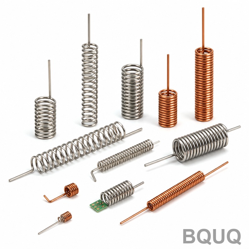
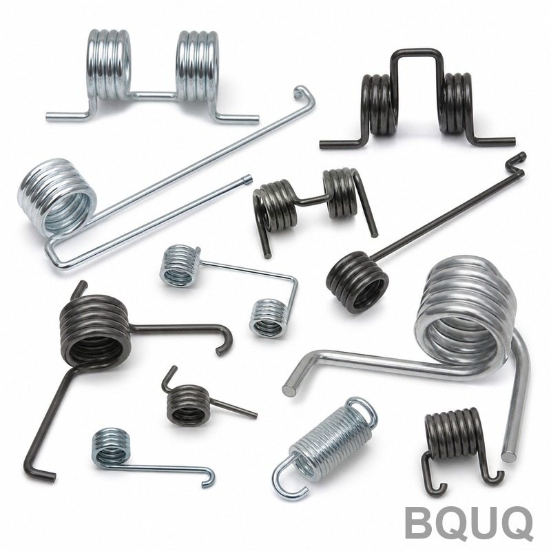
Spring coiling is the process of feeding wire around a mandrel or forming tool to create helical or non-helical shapes, and CNC spring manufacturing automates this with servo-driven axes, real-time feedback, and tooling that achieves tolerances as tight as ±0.01 mm. In a production environment, CNC coiling machines transform raw wire (0.1 mm to 20 mm diameter) into compression, extension, torsion, or conical springs at speeds up to 120 parts per minute, with dimensional repeatability within ±0.5% of the nominal coil diameter. This article explains the mechanics, tolerances, costs, and material considerations of CNC spring manufacturing, using data from BQUQ’s 20 years of precision metalworking in Dongguan.
The Core Mechanics of Spring Coiling
Spring coiling operates on a fundamental principle: wire is fed through a straightener, then driven against a forming tool (the "coiling point") while a mandrel or arbor controls the inner diameter. The wire bends plastically as it wraps around the mandrel, and the pitch is set by the axial feed rate relative to the rotational speed. CNC systems replace the old mechanical cams with two to eight servo axes: wire feed, coiling point position, pitch tool, and cut-off knife. The servo motors provide a resolution of 0.001 mm, allowing the machine to adjust the forming geometry in real time based on laser or encoder feedback.
For a compression spring, the process involves three simultaneous actions: bending (wire wraps around the mandrel), pitching (the pitch tool pushes the wire axially), and feeding (the wire advances at a controlled speed). The spring's free length, coil diameter, and total coils are determined by the ratio of feed speed to mandrel rotation speed. In CNC machines, this ratio is programmed in the G-code or proprietary software, enabling quick changeovers. A typical setup change from one spring design to another takes 15 to 30 minutes on a modern CNC coiler versus 2 to 4 hours on a mechanical cam machine.
Key Capabilities and Tolerance Data
The precision of CNC spring coiling is defined by the wire material, machine rigidity, and tooling condition. For steel wire (EN 10270-1 or ASTM A227), the achievable tolerances are as follows:
| Parameter | Tolerance Range (Standard) | Tolerance Range (Precision) | Typical Machine Speed |
| Wire Diameter | ±0.02 mm | ±0.005 mm | 30-120 parts/min |
| Coil Outer Diameter | ±0.1 mm | ±0.02 mm | Based on wire dia. |
| Free Length | ±1.0% or ±0.5 mm | ±0.2% or ±0.1 mm | Wire feed 0-60 m/min |
| Total Coils | ±0.25 coil | ±0.1 coil | Servo resolution 0.001 mm |
| Pitch Accuracy | ±3% | ±0.5% | Forming force up to 80 kN |
| End Grinding (flatness) | ±0.05 mm | ±0.01 mm | Grinding wheel speed 35 m/s |
These numbers come from BQUQ’s production data on compression springs for automotive and electronics applications. For example, a valve spring with a 10 mm wire diameter and 40 mm outer diameter can hold a free length tolerance of ±0.3 mm on a standard CNC coiler, but with active feedback (measuring the spring after each cycle and adjusting the feed), we hold ±0.1 mm consistently.
Material Selection and Temperature Effects
Wire material determines the coiling force, springback, and maximum operating temperature. Common materials include: - Music wire (ASTM A228): tensile strength 2300-2600 MPa, max temperature 120°C - Oil-tempered chrome silicon (ASTM A401): tensile 1800-2000 MPa, max temperature 230°C - Stainless steel 302 (ASTM A313): tensile 1700-1900 MPa, max temperature 250°C - Inconel X-750: tensile 1200-1400 MPa, max temperature 650°C
CNC coiling machines handle springback by over-bending: the controller calculates the required forming angle based on the wire's elastic modulus and yield strength, then compensates. For a 2 mm music wire, springback is approximately 8-12 degrees; for the same diameter stainless steel, it is 15-18 degrees. The machine stores a material compensation table, so changing the wire spool from steel to stainless requires selecting a new program, not manual recalibration. Temperature affects the process too: in a non-air-conditioned factory in Dongguan (summer ambient 35°C), the wire's lubricant viscosity drops, increasing friction and slightly altering coil diameter. BQUQ uses temperature-compensated servo drives and runs a calibration spring every 200 parts during hot months to maintain ±0.02 mm outer diameter.
Cost Breakdown and Lead Time for CNC Springs
CNC spring manufacturing costs are driven by setup, wire material, and cycle time. For a typical compression spring (2 mm wire, 20 mm outer diameter, 30 mm free length, 10,000 pieces), the cost structure is:
| Cost Component | Percentage of Total | Typical Price per Part (USD) |
| Setup (programming + tooling) | 15% | $0.005 - $0.015 |
| Wire material (EN 10270-1) | 45% | $0.020 - $0.040 |
| Machine time (CNC coiling) | 25% | $0.010 - $0.020 |
| Secondary operations (grinding, shot peening) | 15% | $0.008 - $0.015 |
The total piece price ranges from $0.05 to $0.09 for this size, assuming a 10,000-piece order. Lead times at BQUQ are 3-5 days for prototypes (1-50 pieces) and 10-15 days for production quantities, including heat treatment (tempering at 250-400°C for steel) and surface coating (zinc plating or phosphate). For larger wire diameters (10 mm and above), the cycle time increases by 3-4 times because the feed rate drops to maintain forming force, and the machine may require a pre-heating station to reduce the yield strength, adding 20% to the machine time cost.
Common Defects and How CNC Controls Prevent Them
Even with CNC control, defects occur if parameters drift. The most frequent issues are: 1. Coil diameter variation: caused by inconsistent wire tension or a worn mandrel. CNC systems monitor tension with a load cell (accuracy ±0.5%) and automatically adjust the feed rate. A worn mandrel (wear limit 0.01 mm) is detected by comparing the actual outer diameter to the programmed value after every 50 cycles. 2. Pitch error: occurs when the pitch tool vibrates at high speeds. CNC machines use a vibration-damped tool holder and limit the acceleration to 2 m/s², keeping pitch error under 0.05 mm over a 50 mm length. 3. End coil loops not closed: for compression springs, the last coil must be closed and ground flat. CNC coiling machines use a secondary servo to press the end coil against the mandrel, then an integrated grinding unit removes 0.1-0.3 mm from each end. The flatness tolerance is ±0.01 mm, verified with a dial indicator.
Preventative maintenance is critical: BQUQ replaces the coiling point tool every 50,000 cycles and the mandrel every 200,000 cycles. This keeps the scrap rate below 0.8% on standard steel springs and below 1.5% on exotic alloys.
Practical Recommendations for Engineers
When specifying a CNC spring, provide the following data to avoid miscommunication: wire material and grade, wire diameter with tolerance, free length, solid length, outer or inner diameter, total coils, and operating temperature. Include the load requirements (force at a given deflection) and whether the spring needs end grinding or shot peening. For high-volume production, request a statistical process control report: BQUQ provides CpK values (typically 1.33 or higher) for the critical dimensions. For prototype validation, order 5-10 pieces first to verify the spring rate and fatigue life under your actual load cycle. Do not specify tight tolerances unless functionally necessary: a free length tolerance of ±0.5 mm costs 30% less than ±0.1 mm because it reduces the need for post-coiling measurement and adjustment. Finally, for springs operating above 150°C, specify chrome silicon or stainless steel, and for fatigue applications exceeding 1 million cycles, require shot peening (intensity 0.2-0.4 mm Almen) to increase fatigue life by 30-50%.
FAQ: Spring Coiling and CNC Manufacturing
1. What is the smallest spring size that can be coiled with CNC? At BQUQ, we coil wire from 0.1 mm diameter (micro springs for medical devices) with an outer diameter of 0.5 mm. The limit is the wire tension control, not the forming tool. 2. Can CNC coiling do non-round shapes? Yes, with a programmable coiling point, we can produce square, rectangular, or conical springs. The tolerance for non-round shapes is ±0.1 mm on the cross-section. 3. How does springback affect the final dimensions? Springback is compensated in the program. For a 1 mm music wire, the coil diameter will be 5% larger than the mandrel if not compensated, so we set the mandrel 5% smaller. The machine stores this factor per material. 4. What is the minimum lead time for a custom spring? For a single prototype with standard wire, we can ship in 24 hours. For a production run of 100,000 pieces, the lead time is 2 weeks including tooling and heat treatment. 5. How do you control end grinding flatness? We use a double-disc grinder with a 35 m/s wheel speed and a diamond dresser. The flatness is checked with a surface plate and feeler gauge, achieving ±0.01 mm on springs with a wire diameter above 3 mm.
Conclusion
CNC spring manufacturing transforms raw wire into precise components through servo-controlled bending, pitching, and cutting, achieving tolerances that mechanical cam machines cannot match. By understanding the interplay of wire material, springback, and machine feedback, engineers can specify springs that are both functional and cost-effective. For any spring project, from a 0.1 mm micro spring to a 20 mm heavy-duty compression spring, BQUQ’s CNC coiling lines and 20 years of manufacturing experience in Dongguan are ready to support you. We provide a 12-hour quotation with full dimensional analysis and material suggestions. Send your drawing or sample to sc@bquq.com, or contact us on WhatsApp at +86 13713157787. Visit www.bquq.com for more details on our CNC machining, metal stamping, heat sink, and spring manufacturing capabilities.
Related Articles
- Where to Buy Custom Metal Springs Online: Top 7 Suppliers
- Lightweight Design and Material Upgrade of New Energy and Automobile Chassis Spring
- Hardware spring fatigue failure analysis and life prediction technology
Frequently Asked Questions
What tolerances can CNC spring coiling achieve for wire diameter and coil outer diameter?
For steel wire (EN 10270-1 or ASTM A227), standard wire diameter tolerance is ±0.02 mm, while precision reaches ±0.005 mm. Coil outer diameter standard tolerance is ±0.1 mm, with precision at ±0.02 mm. These are based on BQUQ’s production data for automotive and electronics springs.
How fast can a CNC spring coiling machine produce parts?
CNC coiling machines can produce springs at speeds up to 120 parts per minute, depending on wire diameter and design. Wire feed rates range from 0 to 60 m/min, and forming force can reach up to 80 kN. A typical setup change takes 15 to 30 minutes on a modern CNC coiler.
What wire diameters and materials are supported in CNC spring manufacturing?
CNC coiling machines handle raw wire from 0.1 mm to 20 mm in diameter. Common materials include steel wire per EN 10270-1 or ASTM A227 standards. The process can create compression, extension, torsion, or conical springs with dimensional repeatability within ±0.5% of nominal coil diameter.
How does CNC spring coiling compare to mechanical cam machines in precision and changeover?
CNC systems use two to eight servo axes with 0.001 mm resolution, enabling real-time adjustments via laser or encoder feedback. This achieves tighter tolerances, such as free length precision of ±0.2% or ±0.1 mm, versus ±1.0% or ±0.5 mm standard. Changeover time is 15-30 minutes on CNC versus 2-4 hours on mechanical cam machines.


