
Compound Die Stamping: Definition, Tolerances, and When to Use One
A compound die is a stamping tool that performs multiple operations, such as blanking and piercing, in a single press stroke within one station. You should use a compound die when your part requires high flatness, precise hole-to-edge relationships, and production volumes between 10,000 and 1,000,000 units, where the higher tool cost is offset by faster cycle times and reduced secondary handling.
How a Compound Die Works and Its Core Advantages
In a compound die, the blanking punch and the piercing punch are mounted on the same die plate, but they act in opposite directions relative to the stripper. The die is designed so that the outer edge of the punch blanks the outer profile, while the inner punches pierce holes simultaneously. Because all operations happen in one stroke, the workpiece is never repositioned, which eliminates cumulative positioning errors.
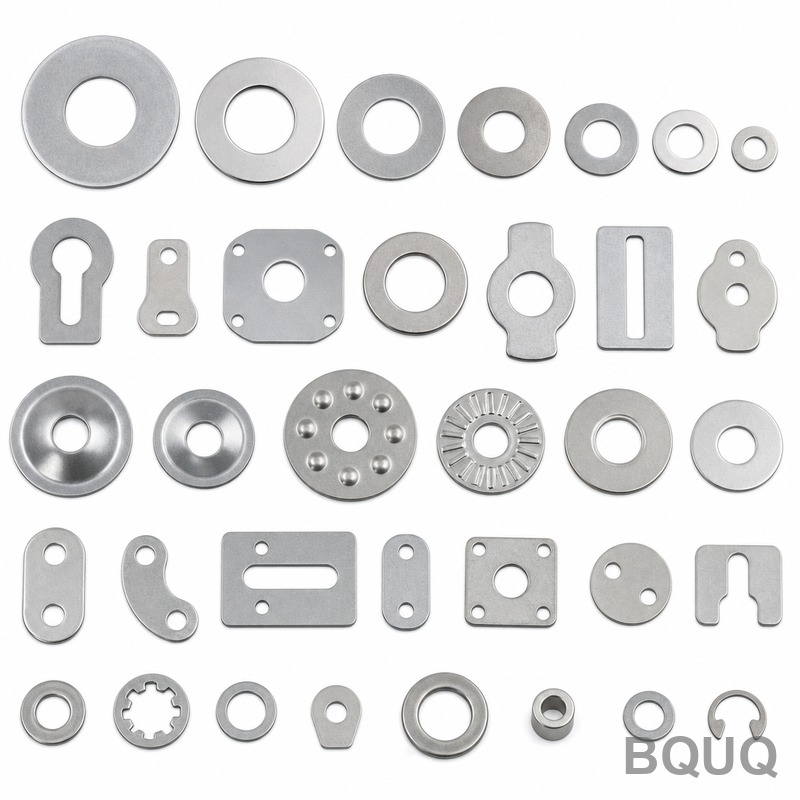
This design delivers two critical engineering benefits. First, the flatness of the finished part is superior because the material is held flat by the stripper plate during the entire operation. Second, the concentricity between the outer profile and internal holes is maintained to within ±0.01 mm, which is difficult to achieve with progressive dies on thin materials. For example, a 0.5 mm thick stainless steel shim can be blanked and pierced with a compound die holding a total flatness of 0.03 mm over a 50 mm diameter, whereas a progressive die would typically yield 0.08 mm flatness.
Compound Die vs Progressive Die vs Single-Stage Die
The decision between die types depends on part geometry, tolerance requirements, and production volume. A single-stage die performs one operation per stroke, a compound die performs multiple operations per stroke in one station, and a progressive die performs multiple operations across multiple stations as the strip advances. The table below provides a direct comparison based on typical factory data from BQUQ production runs.
| Parameter | Compound Die | Progressive Die | Single-Stage Die |
| Tooling Cost (USD) | 4,500 - 12,000 | 8,000 - 30,000 | 1,500 - 4,000 |
| Lead Time for Tooling | 3 - 5 weeks | 6 - 10 weeks | 2 - 3 weeks |
| Tolerance (Hole to Edge) | ±0.01 mm | ±0.03 mm | ±0.05 mm |
| Flatness (0.5 mm material) | 0.03 mm max | 0.08 mm max | 0.10 mm max |
| Cycle Rate (strokes/min) | 120 - 200 | 400 - 800 | 60 - 120 |
| Part Cost per 1000 (USD) | 45 - 90 | 35 - 70 | 80 - 140 |
| Scrap Rate | 15 - 25% | 10 - 15% | 30 - 40% |
| Best Volume Range | 10k - 1M units | 100k - 10M units | Under 5k units |
The cycle rate difference is notable. A compound die runs at 120-200 strokes per minute because the press must handle the full blanking force in one hit. A progressive die achieves 400-800 strokes per minute because each station only performs a portion of the work. However, the compound die's advantage lies in eliminating secondary operations. For a part requiring a countersunk hole and a blanked profile, the compound die produces the finished part in 0.5 seconds, while a progressive die requires 0.8 seconds including strip advancement and the progressive die still requires a separate deburring operation.
Tolerances and Surface Finish Capabilities
Compound dies excel in applications where the hole-to-hole and hole-to-edge dimensions are critical. Because the punches and die are ground as a matched set, the achievable positional tolerance is ±0.01 mm for hole centers and ±0.015 mm for hole-to-edge distances on material up to 3.0 mm thick. For thicker material, up to 6.0 mm, the tolerance relaxes to ±0.02 mm due to the increased deflection of the die plate under higher blanking forces.
The sheared edge quality is another differentiator. A compound die produces a burnish zone of 60-80% of the material thickness on the blanked edge, compared to 40-50% for a progressive die. This is because the material is fully supported on both sides during the blanking operation. For example, on a 2.0 mm thick mild steel part, a compound die yields a burnish zone of 1.4 mm, while a progressive die yields only 1.0 mm. The remaining portion is the fracture zone, which has a rougher surface. For applications like valve plates or shims that require sealing surfaces, the higher burnish ratio directly improves performance.
Material Compatibility and Thickness Limits
Compound dies are suitable for most stamping materials, but the thickness range is limited by the press tonnage and the die construction. The practical thickness range for a compound die is 0.1 mm to 6.0 mm. Below 0.1 mm, the material tends to fold between the punch and die rather than shear cleanly. Above 6.0 mm, the blanking force becomes excessive, and the die components risk cracking. For example, blanking a 6.0 mm thick stainless steel 304 plate with a 50 mm diameter requires approximately 120 tons of force, which demands a heavy-duty die set and a larger press frame.
The typical materials processed include cold-rolled steel (SPCC, DC01), stainless steel (304, 316), aluminum alloys (5052, 6061), brass (H62), and copper (C1100). For aluminum and copper, the compound die can run at higher speeds because the shear strength is lower. A 1.0 mm thick aluminum 5052 part can be blanked at 180 strokes per minute, while the same geometry in stainless steel 304 runs at 120 strokes per minute to reduce die wear.
Cost Breakdown and Economic Justification
The tooling cost for a compound die is higher than a single-stage die but lower than a progressive die. The cost breakdown for a typical compound die used to produce a 30 mm diameter washer with a 10 mm center hole is as follows: design and engineering at 1,200 USD, die plate machining and grinding at 2,800 USD, punch and die insert manufacturing at 1,500 USD, stripper and guide components at 800 USD, and assembly and tryout at 1,200 USD, totaling 7,500 USD. The tryout process typically requires 500-800 test strokes to verify dimensions and adjust the die clearance.
The economic break-even point compared to a single-stage die is approximately 8,000 parts. At 8,000 parts, the compound die's higher tooling cost is recovered through reduced labor and handling. Below 8,000 parts, a single-stage die with two separate operations is more economical. Compared to a progressive die, the compound die is more economical up to 1 million parts. Beyond 1 million parts, the progressive die's higher cycle rate and lower per-part cost become dominant.
Practical Recommendations for Design Engineers
When designing a part for compound die stamping, follow these guidelines to minimize cost and maximize quality. First, keep the minimum hole diameter at least 1.2 times the material thickness. For example, a 0.5 mm thick part requires a minimum hole diameter of 0.6 mm. Smaller holes risk punch breakage and require frequent sharpening. Second, maintain a minimum distance between a hole edge and the blanked edge of at least 1.5 times the material thickness. This prevents the metal between the two edges from tearing during the blanking operation.
Third, avoid sharp internal corners in the blanked profile. Specify a minimum corner radius of 0.5 times the material thickness. Sharp corners create stress concentrations in the die and reduce tool life. Fourth, consider the material grain direction for bending operations. If the part requires bending after blanking, the bend line should be perpendicular to the rolling direction to prevent cracking. Fifth, request a die clearance of 5-8% of the material thickness per side for ferrous materials and 3-5% for non-ferrous materials. This clearance affects the sheared edge quality and the burr height.
Frequently Asked Questions on Compound Die Usage
Question: Can a compound die produce parts with bends or forms? No, a compound die is limited to flat blanking and piercing operations. If your part requires a bend, you need a forming operation in a separate die or a progressive die with a bending station.
Question: What is the typical tool life of a compound die? For mild steel, the tool life is 200,000 to 500,000 strokes before resharpening is required. For stainless steel, the life is reduced to 80,000 to 150,000 strokes. The punch material is typically D2 tool steel hardened to 58-62 HRC.
Question: How do I know if my part is too large for a compound die? The maximum blanking area is limited by the press capacity. A standard compound die can handle blanking forces up to 150 tons, which corresponds to a maximum blanked area of approximately 150 square centimeters in 2.0 mm thick mild steel. Larger parts require a progressive die or a transfer die.
Question: Does a compound die produce burrs? Yes, a compound die produces a burr on the blanked edge, but the burr height is typically 0.02-0.05 mm for material up to 2.0 mm thick. If the application requires a burr-free edge, specify a secondary deburring operation or request a shaved edge die design, which adds 15-20% to the tooling cost.
Conclusion and Next Steps for Your Stamping Project
A compound die is the optimal choice when your part requires high flatness, tight hole-to-edge tolerances, and production volumes between 10,000 and 1,000,000 units. It offers the best balance of tooling cost, cycle time, and part quality for flat parts that need multiple operations. For parts with bends or very high volumes above 1 million units, a progressive die is more appropriate. For low volumes below 8,000 units, a single-stage die is more cost-effective. Evaluate your part geometry and tolerance requirements against the data in this article to make the right decision.
BQUQ has manufactured compound dies for over 20 years in Dongguan, China, serving clients in automotive, electronics, and appliance industries. Our engineering team provides a 12-hour quoting service for compound die projects. Send your part drawings to sc@bquq.com or contact us on WhatsApp at +86 13713157787 to receive a detailed feasibility analysis and cost estimate. Visit www.bquq.com to review our stamping capabilities and quality certifications.


