
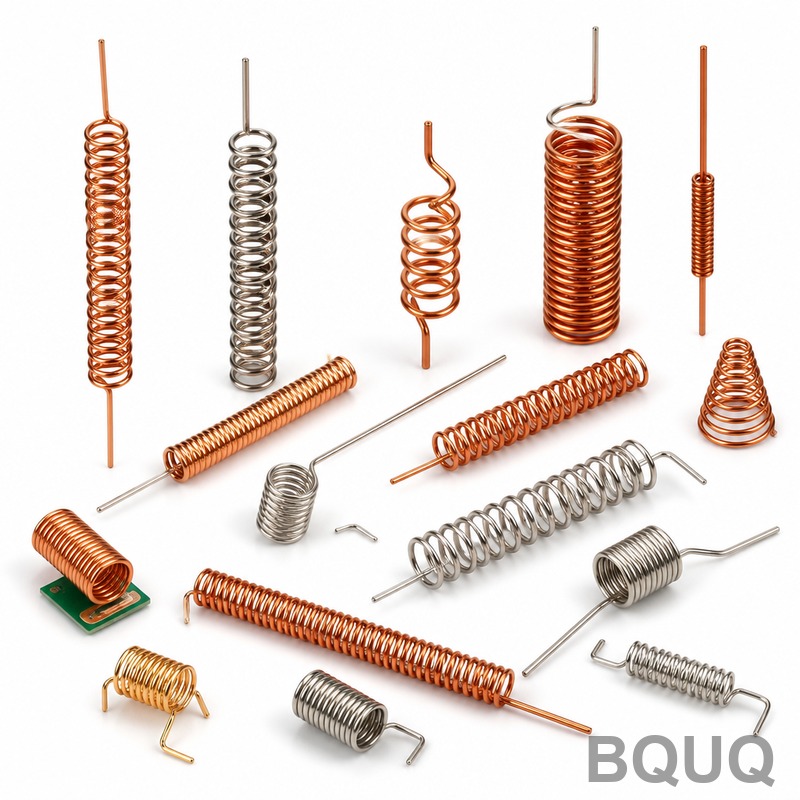
Conical vs Cylindrical Springs: When to Use Each Design?
For applications requiring a progressive spring rate, compact solid height, or resistance to surging at high frequencies, a conical spring is the superior choice; for applications needing a linear, predictable force-deflection relationship within a fixed diameter envelope, a cylindrical spring is the correct design. The decision hinges on three primary factors: space constraints, force profile requirements, and dynamic operating conditions. This article provides a direct engineering comparison, including quantitative data on spring rates, stress distribution, and manufacturing costs, to guide your selection for CNC-machined, stamped, and custom spring applications.
What Is the Fundamental Difference in Force Deflection Behavior?
The cylindrical spring, with its constant coil diameter and pitch, produces a linear spring rate. This means the force increases proportionally with deflection, following Hooke's Law (F = kx) precisely until solid height is reached. In contrast, a conical spring, also known as a tapered or volute spring, has coils of decreasing diameter. As the spring compresses, the larger coils bottom out first, becoming inactive. This reduces the number of active coils, which dynamically increases the spring rate (k) as deflection increases. The result is a progressive spring rate curve, not a straight line. For example, a cylindrical spring with a rate of 10 N/mm will always provide 10 N/mm; a conical spring may start at 8 N/mm, rise to 15 N/mm mid-travel, and finish at 25 N/mm near solid height. This progressive behavior is critical for applications requiring a soft initial response followed by a stiff final response, such as in automotive suspension valves or safety relief mechanisms.
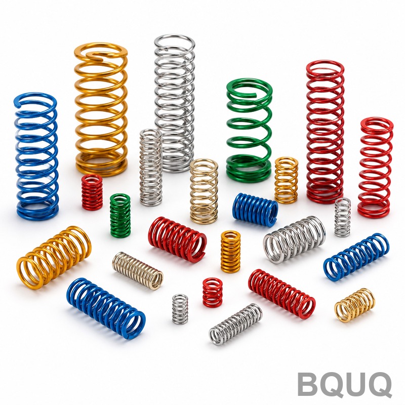
How Does Solid Height Compare Between Conical and Cylindrical Designs?
Solid height is the length of the spring when all coils are touching. For a cylindrical spring, solid height (Ls) is calculated as the number of coils (Nt) multiplied by the wire diameter (d): Ls = Nt * d. For a conical spring, the coils nest inside one another, meaning the solid height is significantly lower. In a fully compressed conical spring, the largest coil sits at the top, and each subsequent coil fits inside the previous one. The theoretical minimum solid height is approximately the diameter of the largest wire plus the thickness of the nested coils, often reducing the solid height by 40% to 60% compared to a cylindrical spring of the same free length and wire diameter. For instance, a cylindrical spring with 10 coils of 5 mm wire has a solid height of 50 mm. A conical spring with the same wire and free length can achieve a solid height of approximately 25 mm to 30 mm. This space-saving attribute is invaluable in tight assemblies like automotive shock absorbers, medical devices, and compact electronic actuators.
When Should You Choose a Conical Spring for Space-Constrained Applications?
You should select a conical spring when the working stroke must be maximized within a limited installation height. Because the solid height is much lower, the available deflection range (free length minus solid height) is larger. Consider a design envelope of 80 mm in height and 40 mm in diameter. A cylindrical spring with a 40 mm outer diameter (OD) might have a free length of 70 mm and a solid height of 40 mm, offering a maximum deflection of 30 mm. A conical spring with a base OD of 40 mm, a top OD of 20 mm, and the same 70 mm free length might have a solid height of only 20 mm, offering up to 50 mm of deflection. This 66% increase in stroke is critical in applications like valve return mechanisms in pneumatic cylinders where the spring must fit inside a bore with a limited stroke length. Additionally, conical springs are preferred when the spring must be designed to avoid coil clash or buckling, as the nesting geometry provides inherent lateral stability.
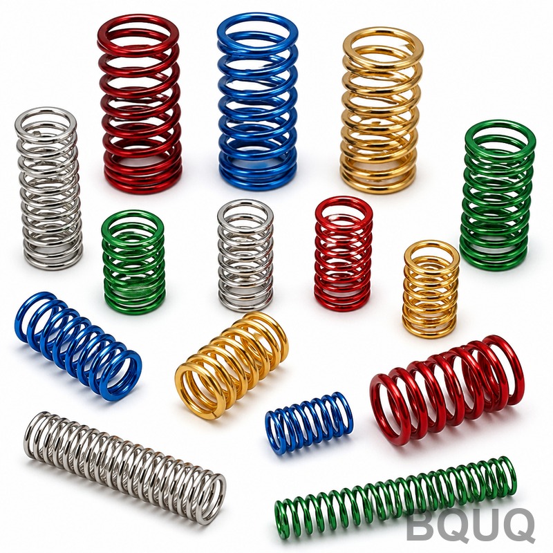
How Does the Stress Distribution Differ and Why Does It Matter?
In a cylindrical spring, stress is uniformly distributed across all active coils under load. The maximum shear stress is calculated using the Wahl factor, which accounts for curvature and direct shear. In a conical spring, stress distribution is non-uniform. The largest coil (at the base) experiences the highest bending moment and stress because it has the largest lever arm. As the smaller coils become inactive, the stress concentration shifts. This means the design must account for higher localized stress at the base coil. For example, a cylindrical spring made of 1.5 mm music wire (ASTM A228) with a mean diameter of 10 mm might operate safely up to 700 MPa. A conical spring with the same wire and base diameter will have a higher stress concentration factor; the base coil might see stress levels exceeding 850 MPa at the same load. Therefore, conical springs often require either a larger wire diameter, a higher-grade material (e.g., chrome silicon, ASTM A401), or a shot-peening process to achieve the same fatigue life as a cylindrical counterpart. Designers must perform finite element analysis (FEA) on conical designs to verify stress margins, especially for cyclic loading exceeding 10^6 cycles.
What Are the Manufacturing and Cost Implications for Each Design?
Cylindrical springs are the default for high-volume production due to their simple geometry. They can be coiled on standard CNC coiling machines at speeds of 30 to 60 parts per minute. Tooling costs are minimal, typically ranging from $200 to $800 for a standard collet and pitch tool. Conical springs require more complex tooling, including a tapered mandrel or specialized CNC coiling head that adjusts the radius continuously during the coiling process. Production speeds are lower, typically 15 to 30 parts per minute. Tooling costs for conical springs are higher, often ranging from $800 to $2,500. Additionally, conical springs may require secondary operations like grinding (for square ends) which is more difficult due to the varying diameter, adding $0.05 to $0.15 per part versus $0.02 to $0.05 for cylindrical. For very small runs (under 500 pieces), the cost difference is negligible, but for runs over 10,000 pieces, cylindrical springs are significantly more economical. The table below summarizes the key quantitative distinctions.
| Parameter | Cylindrical Spring | Conical Spring |
| Spring Rate Profile | Linear (constant k) | Progressive (increasing k) |
| Typical Solid Height Reduction | Baseline (100%) | 40% to 60% lower than cylindrical |
| Maximum Shear Stress Location | Uniform across coils | Highest at base (largest coil) |
| Tooling Cost (USD) | $200 - $800 | $800 - $2,500 |
| Production Speed (parts/min) | 30 - 60 | 15 - 30 |
| Standard Tolerance (Rate) | +/- 5% | +/- 10% |
| Free Length Tolerance (mm) | +/- 0.25 mm | +/- 0.50 mm |
| Typical Material Cost Impact | Lower (standard wire) | Higher (often requires upgraded alloy) |
Which Applications Demand a Cylindrical Spring Over a Conical One?
You must use a cylindrical spring when a precise, predictable force is required for a specific deflection. This is critical in precision mechanical assemblies like fuel injectors, pressure relief valves in hydraulic systems, and load cells. In these cases, a linear rate ensures that the force at a specific lift height is repeatable. For example, a fuel injector spring must provide exactly 45 N at a 2.0 mm lift and 90 N at a 4.0 mm lift. A conical spring would provide a non-linear output, making calibration impossible. Additionally, cylindrical springs are preferred when you need maximum force capacity per unit volume. Because the stress is more evenly distributed, a cylindrical spring can be designed with a smaller wire diameter to achieve the same load, reducing material weight. Cylindrical springs are also the standard for applications with a fixed outer diameter guide, such as a spring inside a drilled pocket, where the conical spring's tapering would cause it to tilt or bind.
How Do Dynamic Characteristics (Surging and Natural Frequency) Influence the Choice?
Surging is an undesirable condition where the spring oscillates at its natural frequency, causing coil impact and premature failure. Cylindrical springs are highly susceptible to surging when subjected to high-frequency actuation, such as in engine valve trains operating above 3,000 RPM. The uniform pitch allows a compression wave to travel the entire spring length. Conical springs, due to their non-uniform coil spacing and progressive engagement, inherently dampen these waves. The varying pitch and coil diameter disrupt the harmonic resonance, increasing the natural frequency by up to 30% compared to a cylindrical spring of the same mass and free length. For example, a cylindrical spring might have a natural frequency of 100 Hz, while a conical spring with similar dimensions might resonate at 130 Hz. For high-speed applications (above 50 Hz), a conical spring is often the only viable coil spring option without adding complex dampers or using titanium alloys. If space allows, a dual-rate cylindrical spring (two springs stacked) can mimic this effect, but it adds assembly complexity.
What Are the Practical Guidelines for Material Selection and Tolerances?
For cylindrical springs, standard materials like oil-tempered chrome silicon (ASTM A401) and stainless steel 302 (ASTM A313) are used with standard tolerances of +/- 5% on the spring rate and +/- 0.25 mm on free length. For conical springs, the progressive rate makes tolerance control more challenging; a standard manufacturing tolerance is +/- 10% on the rate. This wider tolerance is due to cumulative variations in coil diameter and pitch. In terms of operating temperatures, cylindrical springs made of Inconel X-750 can operate up to 600°C, while conical springs face a thermal limitation due to the nested coils, which reduce surface area for heat dissipation; derating to 500°C is recommended. When designing for a conical spring, specify the ratio of base diameter to top diameter. A ratio exceeding 3:1 is difficult to manufacture without coil slippage. A practical limit is 2.5:1 for wire diameters above 2 mm. For both types, shot peening is recommended if the stress exceeds 60% of the tensile strength.
Conclusion
In summary, the choice between conical and cylindrical springs is a function of three engineering priorities: space efficiency, force linearity, and dynamic stability. Choose a conical spring for compact assemblies requiring a progressive rate and low solid height, but be prepared to manage higher stress concentrations and wider tolerances. Choose a cylindrical spring for applications demanding linear force, tight tolerances, and cost-effective high-volume production. Always simulate the final assembly with FEA to verify stress, fatigue life, and clearance, particularly for conical designs with nested coils.
What Is the Lead Time for Custom Spring Manufacturing at BQUQ?
At BQUQ, standard cylindrical spring prototypes are produced in 3-5 business days, while conical spring prototypes require 5-7 business days due to more complex tooling setup. Production lead times for orders under 10,000 pieces are typically 2-3 weeks, depending on material availability and surface treatment requirements.
How Do I Specify a Conical Spring for a Quotation?
You must provide the wire diameter, base OD, top OD, free length, number of active coils, and the required force at two different heights (e.g., 50 N at 10 mm and 120 N at 20 mm). This data is essential for our engineers to calculate the progressive rate and verify stress levels.
Can a Conical Spring Be Used for Tension (Extension) Applications?
Yes, but it is uncommon. Conical tension springs are used when a very low initial tension and a high final load are needed. However, they are more difficult to manufacture because the end hooks must be positioned on different diameters, which can cause bending moments. We recommend a cylindrical tension spring unless space is extremely limited.
What Surface Treatments Are Recommended for Conical Springs?
For conical springs, we recommend shot peening to induce compressive residual stress, which is critical because the base coil experiences high stress. This is followed by either zinc plating (for indoor use) or a black oxide finish. For corrosion resistance in marine environments, electroless nickel plating is preferred, though it adds approximately 15% to the part cost.
How Does Wire Diameter Affect the Minimum Achievable Conical Spring Diameter?
The minimum top coil diameter must be at least 3 times the wire diameter to allow for coiling without fracture. For example, with a 2 mm wire, the smallest top OD is 6 mm. The base diameter can be as large as the design envelope allows, but the ratio of base to top should not exceed 2.5:1 for manufacturability.
When Should I Consider a Machined Spring Instead of a Coiled Spring?
If your conical or cylindrical spring design requires a non-circular cross-section, mounting features (like flanges), or extremely tight tolerances (+/- 0.01 mm on the rate), a CNC-machined spring from solid bar stock is the right choice. Machined springs are more expensive (costing $20-$100 per unit versus $1-$5 for coiled), but they offer superior consistency and can be made in materials that are not coilable.
For a detailed feasibility review and a DFM (Design for Manufacturing) analysis, send your CAD file or specifications to our engineering team. We provide rapid quoting within 12 hours. Contact us at Email: sc@bquq.com, WhatsApp: +86 13713157787, or visit www.bquq.com for immediate assistance.


