Design for Stamping: Best Practices and Common Mistakes to Avoid
**The Direct Answer:** Designing for metal stamping is a balance between material utilization, tooling longevity, and dimensional accuracy. The best practices involve adhering to specific bend radii, hole-to-edge distances, and tolerances (typically ±0.1 mm for standard features), while the most common mistakes include specifying sharp internal corners, ignoring springback, and designing features that require complex, multi-stage dies. Correcting these errors upfront can reduce part cost by 15-30% and cut lead times by 2-4 weeks.
---
Introduction: Why Stamping Design Dictates Your Bottom Line
At BQUQ, with two decades of CNC machining and metal stamping experience in Dongguan, we process over 200 tons of steel and aluminum monthly. Our engineers see the same design flaws repeatedly. A single un-toleranced dimension or an impossible bend radius can force a transfer from a progressive die to a compound die, doubling your tooling cost. This article outlines the precise engineering rules we use to evaluate customer files daily, ensuring manufacturability without sacrificing performance.
H2: Critical Material Selection and Thickness Constraints
The first decision is material grade and thickness, which dictates press tonnage and die wear. For sheet metal stamping, we recommend maintaining a material thickness (T) between 0.3 mm and 6.0 mm for standard progressive dies. Above 6.0 mm, you enter heavy stamping territory requiring hydraulic presses (800-ton capacity) and significantly slower cycle times.
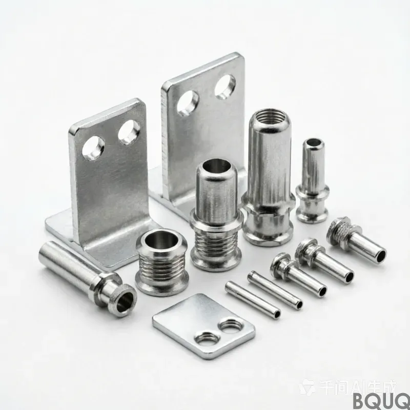
**Key Specifications:** - **SPCC / DC01 (Cold Rolled Steel):** Yield strength ~280 MPa. Ideal for brackets and chassis. Cost baseline: $0.85/kg. - **SUS304 (Stainless):** Work-hardens rapidly. Requires 20% more press force than steel. Cost: $2.40/kg. - **5052 Aluminum:** Excellent formability but 70% the strength of steel. Maximum bend radius must be 1.5T to avoid cracking.
**Common Mistake:** Specifying aluminum for a high-wear sliding component. Aluminum's galling tendency increases die wear by 40%, requiring DLC coatings that add $500 to tooling cost.
H2: Bend Radius and Springback Compensation: The Math
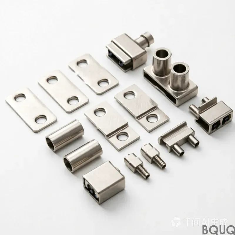
The most frequent rejection reason in our QC department is dimensional drift on bent features. The rule of thumb for the minimum inside bend radius is **1.0T** for mild steel and **1.5T** for aluminum. If you design a sharp 90-degree corner with a radius less than 0.5T, the material will fracture on the outer surface.
**Springback is the hidden variable.** For a 90-degree bend in 1.5 mm thick SPCC, the material will spring back approximately 2-3 degrees after release. Our dies are built with a correction angle (over-bend) to compensate. However, if you specify a tolerance of ±0.5 degrees on a bend angle, we must add a secondary coining operation, increasing piece-part price by 15%.
**Real Data Table: Minimum Bend Radii and Springback Factors**
| Material | Thickness (T) | Min Inside Radius | Springback Angle (90° bend) | Recommended Die Clearance | :--- | :--- | :--- | :--- | :--- | Cold Rolled Steel (SPCC) | 1.5 mm | 1.5 mm (1.0T) | 2.5° | 5-7% of T per side | Stainless Steel (SUS304) | 1.5 mm | 2.25 mm (1.5T) | 5.0° | 8-10% of T per side | Aluminum (5052-H32) | 2.0 mm | 3.0 mm (1.5T) | 4.0° | 6-8% of T per side | Brass (C2680) | 1.0 mm | 0.8 mm (0.8T) | 1.5° | 4-5% of T per side |
|---|
*Table 1: Data from BQUQ die tryout reports, 2024.*
H2: Hole, Slot, and Edge Distance Requirements
Punching holes is straightforward, but proximity to edges and bends creates distortion. For a clean cut without tearing the web, the distance from the edge of a hole to the edge of the part must be **at least 1.5T**. If this distance is less, the material will bulge or deform.
**Critical Parameters for Piercing:** - **Minimum Hole Diameter:** Must be equal to or greater than material thickness (D ≥ 1.0T). For a 0.5 mm thick sheet, a 0.4 mm hole is impossible without micro-punching, which is 3x more expensive. - **Hole-to-Bend Distance:** The edge of a hole must be at least **2.5T + R** (bend radius) away from the bend line. Otherwise, the hole will be pulled into an oval shape during the forming stroke. - **Slot Width:** Minimum slot width is 1.0T. For example, a 0.8 mm wide slot in 1.0 mm steel requires a custom ground punch, adding a $150 tooling charge.
**Common Mistake:** Designing a heat sink with fins requiring slots closer than 1.5T. This forces us to use a chemical etching process instead of stamping, raising unit cost from $0.40 to $2.10.
H2: Tolerances and Surface Finish: What is Actually Achievable
Many customers request tight tolerances without understanding stamping limitations versus machining. While CNC machining holds ±0.01 mm, standard stamping holds:
- **Formed Features (Bend to Hole):** ±0.10 mm. - **Pierced Holes (Position):** ±0.05 mm. - **Flattened Length:** ±0.15 mm.
If you require tighter than ±0.05 mm on a stamped surface, we must add a secondary operation like coining or shaving. This adds a second press hit and doubles the cycle time. For surface finish, standard stamped edges have a shear zone of 1/3T and a break zone of 2/3T. If you need a fully sheared edge (for a bearing surface), specify a shaved edge—but this increases cost by 25%.
H2: The Economic Impact of Die Complexity (Progressive vs. Compound)
Your design dictates the die type. A compound die (one stroke for blanking and piercing) is cheaper (tooling $3,000-$8,000) but limited to flat parts. A progressive die (multiple stations) handles complex bends but tooling ranges from **$10,000 to $50,000** depending on the number of stations.
**Cost Breakdown Example:** - **Simple Bracket (4 holes, 2 bends):** Progressive die, 5 stations. Tooling: $12,000. Part cost: $0.35/piece at 10,000 units. - **Complex Chassis (12 holes, 6 bends, lances):** Progressive die, 14 stations. Tooling: $38,000. Part cost: $1.20/piece at 10,000 units.
**Common Mistake:** Designing a part that requires "flying" (in-die tapping). While we offer it, tapping in-die adds $4,000 to tooling and reduces stamping speed from 80 SPM to 45 SPM. If your thread is M3 or smaller, we recommend specifying a self-clinching nut instead—it is faster and more reliable.
H2: FAQ-Style Tips for Design Engineers
**Q: Can I have a sharp internal corner (0.1 mm radius) in a stamped part?** A: No. Sharp internal corners create stress risers and require EDM machining on the die. The minimum radius we recommend is 0.25 mm, but 0.5 mm is optimal for die longevity. Without a radius, the punch breaks within 50,000 hits instead of 500,000.
**Q: How do I avoid distortion on large flat panels?** A: Specify a material thickness above 1.2 mm and add stiffening ribs (lances) of 0.5T depth. Alternatively, design relief holes at the corners of cutouts. This prevents the "oil canning" effect common in 0.8 mm panels.
**Q: What is the optimal part size for cost efficiency?** A: Parts should fit within a 250 mm x 250 mm die area to use standard press sizes (60-110 tons). If your part exceeds 300 mm in length, we move to a larger press (160 tons), increasing the hourly rate from $60 to $90.
Conclusion: Send Us Your DFM Analysis
Designing for stamping is about respecting the material flow. By adhering to the 1.0T bend radius rule, maintaining 1.5T edge distances, and accepting standard tolerances of ±0.1 mm, you ensure your part is manufacturable on the first try. At BQUQ, our engineers review every file for these specific failure points before quoting.
We provide a complete Design for Manufacturability (DFM) report within 12 hours of receiving your CAD file. We will flag every potential cracking, distortion, or tolerance issue and offer alternative designs to reduce your cost.
**Get your instant project review today:** - **Email:** sc@bquq.com - **WhatsApp:** +86 13713157787 - **Website:** www.bquq.com
Send us your 3D model (STEP or IGES) and target quantity for a precise quote and free stamping design optimization.
Related Articles
- Design for Stamping: 7 Blanking Layout Rules to Cut Scrap Cost by 18% in 2025
- Stamping Lubricant Selection 2024: Balancing Die Life, Part Quality, and Environmental Compliance
- How Metal Stamping Improves Heat Sink Efficiency
Frequently Asked Questions
What is the recommended material thickness range for standard progressive die stamping?
For standard progressive dies, we recommend maintaining material thickness between 0.3 mm and 6.0 mm. Above 6.0 mm, parts enter heavy stamping territory requiring hydraulic presses with 800-ton capacity, which significantly slows cycle times.
What are the minimum inside bend radii for steel and aluminum, and why does it matter?
The minimum inside bend radius is 1.0T for mild steel and 1.5T for aluminum. Designing a sharp 90-degree corner with a radius less than 0.5T will cause the material to fracture on the outer surface, leading to part rejection.
How does springback affect bend tolerances and part cost?
For a 90-degree bend in 1.5 mm thick SPCC steel, the material springs back approximately 2-3 degrees after release. If you specify a tolerance of ±0.5 degrees on a bend angle, we must add a secondary coining operation, which increases piece-part price by 15%.
What is the cost impact of designing for metal stamping correctly?
Correcting design errors upfront can reduce part cost by 15-30% and cut lead times by 2-4 weeks. Avoiding issues like sharp internal corners and springback also prevents tooling cost increases, such as a transfer from progressive to compound dies doubling tooling expense.