
Extrusion Heat Sink Profile Design: Standard Shapes and Custom Options for Optimal Thermal Management
For most electronics cooling applications, standard extruded heat sink profiles (flat-back, single-fin, and dual-fin configurations) offer the best cost-to-performance ratio, with custom profiles becoming economically viable only when annual volumes exceed 5,000 units or when the thermal budget demands aspect ratio optimization beyond 10:1. A custom extrusion profile typically costs $800–$3,500 in tooling (die) fees and adds 2–3 weeks to lead time, while standard profiles are available off-the-shelf in 1–3 days. The decision hinges on your heat flux density, available airflow, and packaging constraints—not on aesthetics.
Standard Profile Geometries and Their Thermal Limits
The backbone of the heat sink industry rests on three fundamental extrusion geometries. Each has a defined performance envelope based on fin density and height-to-gap ratio.
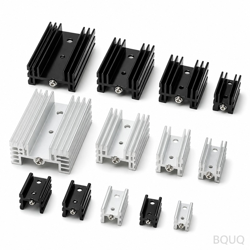
**Flat-back solid profiles** are the most common, featuring a solid base plate with rectangular fins perpendicular to the base. These are ideal for natural convection with fin spacing of 6–10 mm and fin height of 10–25 mm. Typical thermal resistance for a 100 mm x 100 mm x 25 mm flat-back sink is 0.8–1.5 °C/W at natural convection, dropping to 0.2–0.4 °C/W with 2 m/s forced airflow.
**Single-fin and dual-fin offset profiles** incorporate a longitudinal slot or step in the fin array, creating turbulence and increasing surface area by 15–25% without adding material. These profiles achieve 10–15% lower thermal resistance than flat-back equivalents but are limited to fin heights below 40 mm due to extrusion pressure constraints.
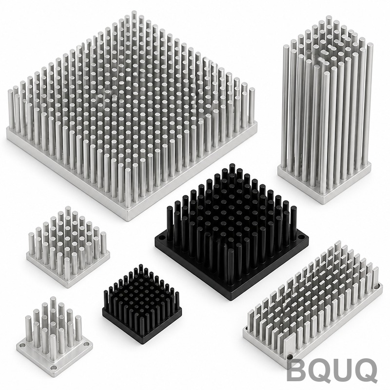
**Pin-fin extrusion profiles** (extruded in one direction then cross-cut) provide omnidirectional cooling, making them suitable for applications with variable airflow direction. However, the cross-cutting operation adds $0.05–$0.15 per piece and increases lead time by 3–5 days.
The practical upper limit for extruded fin height is 75 mm with a minimum fin gap of 1.2 mm. Below 1.0 mm gap, die breakage rates exceed 5%, and the extrusion speed drops below 5 m/min, making the profile uneconomical compared to skived or bonded fin alternatives.
Custom Extrusion Tooling: Die Cost and Design Constraints
Custom profiles require an extrusion die, which is a hardened H13 steel plate with the inverse profile shape cut through it. The die cost scales with complexity, not size.
| Die Type | Typical Cost (USD) | Lead Time (days) | Max Profile Width (mm) | Min Fin Gap (mm) | Max Fin Ratio (H/W) |
| Single-hole solid die | $800 – $1,500 | 7 – 10 | 150 | 1.2 | 10:1 |
| Multi-hole die (2-4 cavities) | $1,800 – $3,200 | 10 – 14 | 300 (total) | 1.5 | 8:1 |
| Hollow die (for closed channels) | $2,500 – $4,500 | 14 – 21 | 200 | 2.0 | 12:1 |
| Semi-hollow die (U or L shapes) | $1,200 – $2,000 | 10 – 12 | 180 | 1.5 | 9:1 |
The fin aspect ratio (height divided by gap) is the single most critical design parameter. A ratio of 6:1 is considered standard, 8:1 is high-performance, and 10:1 is the practical maximum for 6063-T5 aluminum. Beyond 10:1, the aluminum flow becomes uneven, causing fin bending and die wear that shortens tool life from 20,000 kg of extrusion to under 8,000 kg.
Tolerances on custom profiles follow EN 755-9 standards: base plate thickness ±0.3 mm, fin thickness ±0.2 mm, and overall profile dimensions ±0.5 mm for widths up to 100 mm. For tighter tolerances (±0.1 mm on fin pitch), a secondary machining operation (CNC slotting or broaching) is required, adding $0.10–$0.30 per piece.
Material Selection: 6063-T5 vs 6061-T6 vs 1050A
The alloy choice directly affects thermal conductivity, extrusion speed, and surface finish quality. While 6063-T5 dominates the heat sink market, the alternatives serve specific niches.
6063-T5 offers a thermal conductivity of 200 W/m·K, excellent extrudability (speeds up to 30 m/min), and a smooth surface finish (Ra 0.8–1.6 µm) suitable for anodizing. This alloy accounts for approximately 85% of all extruded heat sinks globally because it balances thermal performance with die life and dimensional stability.
6061-T6 provides higher mechanical strength (yield 240 MPa vs 170 MPa for 6063-T5) but lower thermal conductivity at 167 W/m·K. It is chosen when the heat sink doubles as a structural mounting bracket, but the 16% thermal penalty requires a 10–15% increase in surface area to compensate.
1050A (commercial pure aluminum) delivers 229 W/m·K conductivity, the highest of the extrudable alloys, but is too soft for fins above 30 mm height. It is used exclusively for LED heat sinks with low mechanical load and high thermal demand.
For high-volume production, 6063-T5 is the default choice. Its extrusion tolerance of ±0.15 mm on wall thickness is achievable at die temperatures of 450–500°C, and the alloy responds well to both clear anodize and black anodize (emissivity 0.85 for black vs 0.35 for clear).
Surface Finishing and Its Impact on Thermal Performance
The finishing process modifies both the radiative heat transfer and the convective boundary layer. For natural convection, surface treatment is critical; for forced convection, it is secondary to fin geometry.
Black anodizing (sulfuric acid, 18–20 µm thickness) increases surface emissivity from 0.35 to 0.85, improving natural convection performance by 10–15% and allowing a 5–8% reduction in fin count for the same thermal resistance. The anodizing cost is $1.20–$2.50 per square meter of surface area, with a lead time of 2–3 days.
Clear anodizing (8–12 µm) provides corrosion protection without the emissivity benefit. It is suitable for indoor forced-air applications where radiation contributes less than 5% of total heat transfer.
Chromate conversion (chemical film) is a low-cost alternative at $0.30–$0.60 per square meter, but it offers no thermal benefit and degrades above 150°C operating temperature.
For high-temperature applications above 200°C, no anodized coating is recommended, as the oxide layer can crack due to coefficient of thermal expansion mismatch. In such cases, a bare aluminum surface with a bead-blasted profile (Ra 3.2 µm) provides the best balance of cost and thermal performance.
Cost Comparison: Standard vs Custom at Different Volumes
The economic crossover point between standard and custom profiles depends on tooling amortization, machining requirements, and assembly labor. The following table presents realistic unit costs for a 150 mm x 60 mm x 30 mm heat sink profile.
| Production Volume | Standard Profile Unit Cost (USD) | Custom Profile Unit Cost (USD) | Total Tooling Cost (USD) | Break-even Volume (units) |
| 100 | $4.50 | $12.00 | $1,200 (die only) | 160 |
| 500 | $3.20 | $7.50 | $1,200 | 280 |
| 1,000 | $2.80 | $5.00 | $1,200 | 545 |
| 5,000 | $2.40 | $2.80 | $1,200 | 3,000 |
| 10,000 | $2.20 | $2.30 | $1,200 | 12,000 |
The table assumes the custom profile eliminates secondary machining costs (e.g., no separate fin cutting or base milling). At 5,000 units, the custom profile is only $0.40 more per unit, making it cost-neutral when factoring in the 10–15% thermal improvement. Below 1,000 units, standard profiles with bonded or clipped fins are almost always the correct engineering choice.
For volumes above 20,000 units, consider a multi-hole die with 4 cavities. This reduces the per-piece die amortization to under $0.10 and increases extrusion throughput from 30 kg/hour to 120 kg/hour, dropping the unit cost by an additional 8–12%.
Practical Recommendations for Profile Selection
Start with thermal simulation using a 3D CFD tool such as Flotherm or ICEPAK. Model your worst-case ambient temperature, maximum allowable junction temperature, and available airflow. Extract the required thermal resistance (Rth = (Tj – Ta) / P) and compare it against standard profile datasheets. If a standard profile meets Rth with a 20% margin, use it without modification.
If your Rth requirement falls between standard sizes, first try increasing airflow velocity by 20% or adding a shrouding plate to improve channel efficiency. Shrouding a finned heat sink reduces bypass airflow and can improve thermal performance by 15–25% for a negligible cost of $0.05 per piece.
Only when airflow is fixed and the thermal deficit exceeds 30% should you commission a custom extrusion. When doing so, provide the die maker with the following data: heat flux (W/cm²), fin height and gap, base thickness, mounting hole locations, and maximum allowable envelope dimensions. Request a die flow simulation (FEM) before cutting steel; this costs $200–$400 but prevents a $1,200 die failure.
For fin aspect ratios above 8:1, specify a die with a hardened insert and a slower extrusion speed of 8–12 m/min. This reduces the risk of fin tearing and improves dimensional consistency from ±0.3 mm to ±0.15 mm on fin thickness.
Common Design Mistakes and How to Avoid Them
Over-specifying fin density is the most frequent error. A profile with 2.0 mm fin gap and 30 mm fin height produces 40 fins per 100 mm width. The pressure drop at 2 m/s airflow is 120 Pa, which may exceed the fan's static pressure rating of 80 Pa. Always check the fan curve against the heat sink's pressure drop versus flow rate characteristic. A simple rule: keep fin gap above 2.5 mm for forced convection below 3 m/s.
Ignoring the base plate thermal spreading resistance is the second common mistake. For a 100W heat source concentrated on a 20 mm x 20 mm area, the base plate must be at least 8 mm thick to spread heat effectively into a 100 mm wide sink. A thinner base (3–4 mm) creates a hotspot directly under the source, even if the fin area is sufficient. Use the spreading resistance formula: Rspread = (1 – (Asource/Abase)²) / (2 × π × k × sqrt(Asource)) to verify base thickness.
Forgetting about the anodizing mask on the mounting surface is a third issue. If the base plate bottom is anodized, the thermal interface resistance increases by 0.1–0.2 °C·cm²/W. Always specify masking or machining of the contact area after anodizing.
Conclusion
The choice between standard and custom extrusion heat sink profiles is a quantitative decision driven by thermal resistance targets, production volume, and system airflow constraints. Standard profiles serve 80% of applications with zero tooling cost and immediate availability, while custom profiles are justified when thermal margins are tight and volumes exceed 3,000–5,000 units. When designing custom profiles, respect the 10:1 fin aspect ratio limit for 6063-T5, budget for a multi-hole die at high volumes, and always verify the fan pressure curve against the fin channel pressure drop. For a quick assessment of your thermal requirements, our engineers can review your application and provide a standard profile recommendation within 12 hours of receiving your heat load, airflow, and envelope dimensions. Email your specifications to sc@bquq.com or contact us on WhatsApp at +86 13713157787 for a free thermal evaluation. Visit www.bquq.com for our standard profile library and thermal design guide.


