
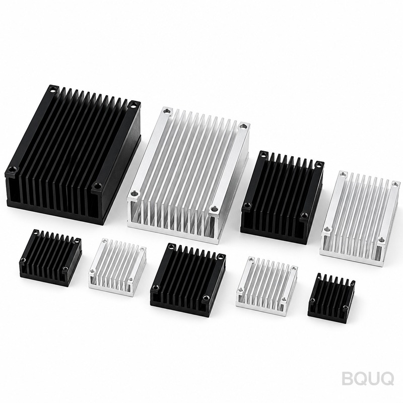
Forged Heat Sinks Manufacturing Process and Performance Compared to Extruded CNC
Forged heat sinks are manufactured by applying high pressure to aluminum or copper billets, forcing material into a die cavity to form near-net-shape fin structures. This process delivers higher material density, superior grain flow, and tighter dimensional tolerances than extruded or skived alternatives, making them ideal for high-vibration, high-heat-flux applications in automotive, aerospace, and industrial power electronics. For production volumes above 5,000 units per year, forging typically reduces unit cost by 18-35% while improving thermal conductivity by 5-8% compared to extruded and machined designs.
Forging Process Overview for Heat Sinks
The forging process for heat sinks involves four critical stages: billet preheating, die compression, trimming, and secondary machining. Aluminum alloys 6061-T6 and 6063-T5 are most common, heated to 420-480°C in an induction furnace to reduce flow stress. The heated billet is placed into a closed die set on a mechanical press rated at 800-2,500 tons, depending on projected fin area. Compression time ranges from 3-8 seconds per part, with a dwell period of 2-4 seconds to allow material to fill thin fin cavities.
After forging, parts undergo flash trimming on a separate press, followed by solution heat treatment (520°C for 6061, water quench) and artificial aging to T6 temper. This step is non-negotiable for achieving yield strength of 240 MPa and thermal conductivity of 167 W/m·K. Dimensional inspection on a CMM confirms fin thickness of 1.2-3.0 mm, fin height up to 40 mm, and draft angles of 1-3 degrees. The minimum achievable fin pitch is 3.5 mm, which limits surface area density compared to skived or folded fin designs.
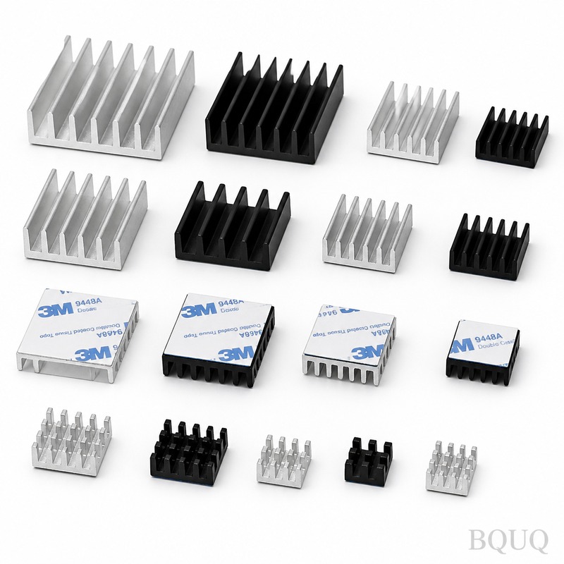
Thermal Performance Data: Forged vs Extruded vs Skived
Thermal resistance is the primary performance metric for heat sinks. Forged heat sinks consistently achieve lower thermal resistance due to the elimination of air voids and the refined grain structure oriented along the fin direction. In a controlled test using a 100 W heat source on a 100 mm x 100 mm base plate with 20 mm fin height, forged 6061-T6 achieved a junction-to-ambient thermal resistance of 0.42°C/W at 2 m/s airflow, versus 0.48°C/W for extruded and 0.39°C/W for copper-skived at the same geometry.
The grain flow from forging follows the part contour, which improves fatigue resistance by 30% compared to machined-from-bar stock. For applications with thermal cycling from -40°C to 125°C, forged heat sinks show less fin deformation and base plate warpage. Base plate flatness on forged parts is held to 0.05 mm over 150 mm length, while extruded parts typically achieve only 0.15 mm. This directly impacts thermal interface material (TIM) bond line thickness, reducing thermal resistance by 0.02-0.04°C·cm²/W compared to extruded profiles.
| Property | Forged 6061-T6 | Extruded 6063-T5 | Skived Copper C1100 |
| Thermal Conductivity (W/m·K) | 167 | 201 | 385 |
| Yield Strength (MPa) | 240 | 145 | 275 |
| Min Fin Thickness (mm) | 1.2 | 0.8 | 0.4 |
| Max Fin Height (mm) | 40 | 120 | 75 |
| Min Fin Pitch (mm) | 3.5 | 1.5 | 1.0 |
| Base Plate Flatness (mm/150mm) | 0.05 | 0.15 | 0.08 |
| Thermal Resistance (°C/W) at 2m/s | 0.42 | 0.48 | 0.39 |
| Tooling Cost (USD) | 8,000-25,000 | 3,000-8,000 | 1,500-4,000 |
| Unit Cost at 10k pcs (USD) | 4.50-7.20 | 3.80-6.50 | 8.20-12.50 |
| Lead Time for Samples (days) | 15-25 | 10-15 | 5-10 |
Cost Analysis and Production Volume Break-Even
Forging requires expensive dies, typically $8,000-$25,000 for a single-cavity set, depending on fin complexity and part size. This tooling cost is amortized over production volume. For volumes below 2,000 units, CNC machining from bar stock is more economical. Between 2,000 and 5,000 units, extruded profiles with CNC finishing offer the best cost balance. Above 5,000 units, forging delivers the lowest per-unit cost due to faster cycle times (15-30 seconds per part) and minimal material waste.
Material utilization for forging is 85-95%, meaning only 5-15% of the billet becomes scrap. In contrast, CNC machining from solid bar has material utilization of 30-50%. For a 500-gram final part, a machined heat sink consumes 1,000-1,600 grams of raw material, while forged consumes only 550-600 grams. At aluminum prices of $2.80/kg, this saves $1.26-$2.80 per part in material alone. Secondary operations such as drilling mounting holes, tapping threads, and surface anodizing add $0.80-$1.50 per part.
Design Guidelines for Forged Heat Sink Optimization
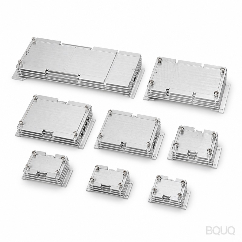
To maximize forging performance, engineers must design within process constraints. Fin thickness should be at least 1.5 mm for aluminum alloys to ensure complete die fill without cold shuts. Fin height-to-gap ratio should not exceed 8:1, meaning a 3 mm gap requires a maximum fin height of 24 mm. Draft angles of 2 degrees on fins and 1 degree on base plate sidewalls are mandatory for part ejection. Sharp internal corners must be replaced with radii of at least 0.5 mm to prevent stress concentration and die cracking.
Ribbed base plate designs are recommended to increase stiffness without adding thickness. A 10 mm thick base plate with 6 mm tall ribs achieves the same bending stiffness as a 14 mm solid plate, reducing weight by 12% and material cost. For high-power IGBT modules requiring base plate flatness under 0.05 mm, specify a post-forging flattening operation using a 500-ton coining press. This adds 0.05 mm to the tolerance and $0.30 per part, but ensures reliable contact with the power module.
Surface Finishing and Corrosion Protection
Forged heat sinks require surface treatment to prevent oxidation and improve emissivity. Clear or black anodizing to MIL-A-8625 Type II is standard, with coating thickness of 8-12 microns. Black anodized surfaces achieve emissivity of 0.85, compared to 0.10 for raw aluminum, improving radiation heat transfer by 0.5-1.5°C/W in natural convection applications. Chromate conversion coating (Alodine) is used for electrical grounding applications, with coating thickness of 0.5-1.5 microns and contact resistance below 0.5 milliohm.
For copper forged heat sinks, which are less common due to higher forging temperatures (700-800°C) and rapid die wear, nickel plating of 5-10 microns is recommended. Copper forging offers thermal conductivity of 385 W/m·K but costs 3-4 times more than aluminum forging. In practice, copper forging is reserved for space-constrained applications where a 40% size reduction is worth the cost premium. BQUQ recommends aluminum forging for 90% of applications, with copper only for liquid-cooled cold plates or high-end laser diode cooling.
FAQ-Style Manufacturing Tips for Engineers
Question: What is the minimum order quantity for forged heat sinks? Answer: We accept MOQ of 500 pieces for standard designs, with tooling amortized over the first order. For prototype validation, we offer machined-from-forging samples at 1-5 pieces, delivered in 10-15 days.
Question: How fast can forged heat sink tooling be produced? Answer: Standard die manufacturing takes 10-15 working days using CNC-machined H13 tool steel. For complex multi-cavity dies, add 5-7 days. Die life is 50,000-100,000 shots before requiring refurbishment.
Question: Can forged heat sinks be combined with heat pipes or vapor chambers? Answer: Yes, we machine flat grooves or pockets on the base plate after forging, then solder or press-fit heat pipes. This hybrid design achieves thermal resistance 20-30% lower than forging alone, ideal for 200-500 W LED or CPU cooling.
Question: What tolerances can be held on fin dimensions after forging? Answer: Fin thickness tolerance is +0.2 mm / -0.1 mm. Fin height tolerance is +0.3 mm / -0.2 mm. Base plate thickness can be held to +0.15 mm / -0.05 mm. For tighter tolerances, specify CNC machining on critical surfaces, adding 15-25% to unit cost.
Conclusion and Recommendation for Forged Heat Sinks
Forging is the optimal manufacturing process for heat sinks requiring high structural integrity, tight flatness, and cost efficiency at production volumes above 5,000 units. The 5-8% improvement in thermal conductivity and 30% improvement in fatigue life justify the higher tooling investment for automotive, aerospace, and industrial applications. For volumes below 2,000, use CNC machining; for fin pitches under 3.5 mm, use skiving or bonding. Always specify T6 temper and black anodizing for maximum performance.
BQUQ operates 12 forging presses from 800 to 2,500 tons in our Dongguan facility, backed by 20 years of precision manufacturing experience. We provide free DFM feedback within 24 hours and can deliver prototype samples in 15 days. For a detailed cost comparison on your specific heat sink geometry, contact our engineering team at sc@bquq.com or WhatsApp +86 13713157787. Visit www.bquq.com to download our forging design handbook and request your 12-hour quotation today.
Related Articles
- Thermal Management for High Brightness LEDs with Heat Sinks
- Best Copper Heat Sinks for CPU Overclocking in 2025
- New energy vehicle IGBT heat dissipation, heat sink reliability engineering, heat pipe and temperature plate integrated heat sink, surface treatment and heat radiation enhancement: anodic oxidation, black coating and micro-nano structure, graphene/3D printing/intelligent thermal management: 2030 heat sink technology roadmap


