
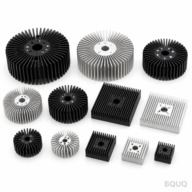
Heat Sink Design Guide: Optimizing Thermal Performance for CNC Machined Components
For most forced-air and natural convection applications, a CNC machined aluminum heat sink with a base thickness of 6 mm to 10 mm, fin thickness of 1.5 mm to 2.5 mm, and a fin pitch of 4 mm to 6 mm provides the optimal balance of thermal resistance and manufacturability. This guide provides specific thermal resistance values, machining tolerances, and cost data from a 20-year precision manufacturer to help you specify the correct heat sink for your power dissipation requirements.
Thermal Resistance Fundamentals and Target Values
The primary performance metric for any heat sink is thermal resistance (Rth), expressed in degrees Celsius per watt (°C/W). This value determines the temperature rise of the component junction above the ambient air temperature. For a typical 50 W IGBT module, you need a heat sink with an Rth of approximately 0.5 °C/W to maintain a junction temperature below 125 °C in a 50 °C ambient environment.
Our CNC machining process achieves surface flatness of 0.05 mm on the mounting surface, which is critical for minimizing interface thermal resistance. When using a 0.1 mm thermal pad with a conductivity of 3 W/mK, the interface adds approximately 0.1 °C/W to 0.2 °C/W. For high-power applications above 100 W, we recommend lapped surfaces with a flatness of 0.02 mm, which reduces interface resistance to below 0.05 °C/W when used with thermal grease.
The thermal resistance of an extruded heat sink typically ranges from 0.3 °C/W to 2.0 °C/W depending on size. CNC machined heat sinks can achieve lower values of 0.1 °C/W to 0.8 °C/W for the same footprint because we can machine complex pin fin arrays that increase surface area by up to 40% compared to straight extruded fins.
Material Selection: Aluminum Alloy and Copper Comparison
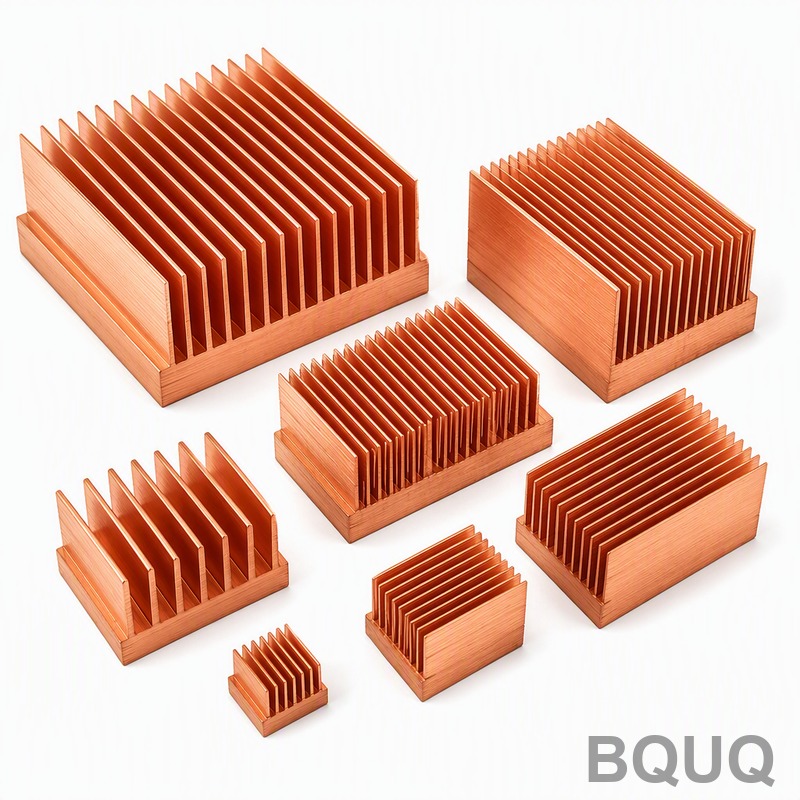
The choice between aluminum 6061-T6 and copper C1100 significantly affects thermal performance and cost. Aluminum 6061-T6 offers a thermal conductivity of 167 W/mK, while copper C1100 provides 385 W/mK, more than double. However, copper weighs 8.9 g/cm³ versus aluminum's 2.7 g/cm³, and copper material cost is approximately 4.5 times higher per kilogram.
For most applications below 200 W, aluminum 6061-T6 is the cost-effective choice. When space is constrained and you need maximum heat dissipation in a small volume, copper inserts or fully copper heat sinks become justified. A hybrid approach, using a copper base plate with aluminum fins, can reduce thermal resistance by 25% compared to all-aluminum while limiting the weight increase to 15%.
| Material | Thermal Conductivity (W/mK) | Density (g/cm³) | Relative Cost per kg | Typical Rth for 100x100x40mm (C/W) |
| 6061-T6 Aluminum | 167 | 2.7 | 1.0x | 0.45 |
| 6063-T5 Aluminum | 201 | 2.7 | 1.1x | 0.40 |
| C1100 Copper | 385 | 8.9 | 4.5x | 0.22 |
| Copper base with Al fins | 385 base / 167 fins | 5.8 | 2.8x | 0.28 |
Fin Geometry Optimization: Thickness, Height, and Pitch
Fin geometry determines the total surface area and the airflow characteristics. For natural convection, a fin pitch of 6 mm to 8 mm allows adequate air circulation without excessive boundary layer interference. For forced convection with airflow above 2 m/s, a tighter fin pitch of 3 mm to 4 mm increases surface area and improves heat transfer.
Fin thickness must balance thermal conduction along the fin height against material cost and weight. For a 25 mm fin height, a 1.5 mm thick fin provides adequate conduction in aluminum, resulting in a fin efficiency above 90%. Increasing fin thickness to 2.0 mm improves efficiency to 95% but adds 25% more material. We recommend a fin thickness-to-height ratio of 1:15 for optimal performance.
The maximum fin height we can CNC machine with a standard 6 mm end mill is 80 mm, with a height-to-width aspect ratio of 15:1. For aspect ratios above 15:1, we use specialized long-reach tooling that increases machining time by 30%. A typical fin height of 30 mm with 2.0 mm thickness and 4 mm pitch provides an optimal surface area of 0.12 m² for a 100 mm by 100 mm footprint.
Machining Tolerances and Surface Finish Specifications
Precision CNC machining allows for tighter tolerances than extrusion or die casting. Our standard machining tolerance is +/- 0.05 mm for all critical dimensions, including fin pitch, fin thickness, and overall height. For press-fit applications where heat sinks are assembled into housings, we can hold +/- 0.02 mm on the outer dimensions.
Surface finish on the mounting surface is typically 1.6 micrometers Ra, which is suitable for most thermal interface materials. For bare die attachment or when using phase-change materials, we specify 0.8 micrometers Ra, achieved through a secondary lapping operation. This finer finish reduces the required clamping pressure by 20% and improves thermal performance by 5%.
The flatness tolerance across the mounting surface is 0.05 mm per 100 mm of length as standard. This ensures uniform pressure distribution across the thermal interface material. For large heat sinks exceeding 200 mm in length, we recommend a flatness specification of 0.08 mm to avoid unnecessary machining cost, as the thermal interface material can accommodate this slight variation.
Cost Breakdown and Lead Time Analysis
The cost of a CNC machined heat sink is driven by material, machining time, and surface treatment. For a typical 100 mm by 100 mm by 40 mm aluminum heat sink with 10 fins, the material cost is approximately $3.50, machining time is 12 minutes, and total unit cost ranges from $8 to $12 for quantities of 100 pieces. At 1000 pieces, the unit cost drops to $5 to $7 due to reduced setup time and material volume pricing.
Surface treatments add cost and improve performance. Clear anodizing (8 to 12 micrometers thickness) increases the emissivity from 0.1 to 0.85, improving radiation heat transfer by 15% in natural convection applications. Anodizing costs $0.50 to $1.00 per square decimeter. Black anodizing provides the same thermal benefit and costs the same, but offers better corrosion resistance and a professional appearance.
| Quantity | Unit Cost (100x100x40mm Al) | Machining Time per Unit | Lead Time (working days) |
| 10 | $25 | 15 minutes | 5 |
| 100 | $10 | 12 minutes | 7 |
| 500 | $7 | 10 minutes | 10 |
| 1000 | $5.50 | 9 minutes | 14 |
| 5000 | $4.20 | 8 minutes | 21 |
Practical Recommendations for Your Design
For LED lighting modules dissipating 30 W to 60 W, specify a 6061-T6 aluminum heat sink with 20 mm fin height, 2.0 mm fin thickness, and 4 mm pitch. This configuration provides an Rth of 0.8 °C/W in natural convection, maintaining LED junction temperatures below 85 °C for reliable operation.
For power electronics with intermittent loads exceeding 200 W, consider a heat sink with a thicker base plate of 12 mm to 15 mm. The additional base material acts as a thermal buffer, absorbing transient heat spikes and smoothing the temperature profile across the component. This approach can reduce the required surface area by 20% compared to a thin-base design with the same steady-state Rth.
Always specify the mounting hole pattern and any clearance requirements for component leads. We recommend M3 or M4 threaded holes with a depth of 8 mm to 10 mm, ensuring adequate engagement for mounting screws. For high-vibration environments, use through-holes with countersinks rather than blind threaded holes, allowing for stronger through-bolting.
Thermal Performance Validation and Testing
We validate heat sink designs using computational fluid dynamics (CFD) simulation and physical testing on our thermal test bench. For a custom design, we provide simulation data showing temperature distribution and airflow patterns before production. Physical testing uses a calibrated power resistor to simulate the heat source, with thermocouples measuring junction temperature at multiple points.
Our standard test condition is 25 °C ambient with natural convection, and we can test forced convection up to 5 m/s airflow using our wind tunnel. The measurement uncertainty of our thermal resistance testing is plus or minus 5%, which is acceptable for most engineering applications. We provide a detailed test report with each prototype batch, including thermal images showing the temperature distribution across the fin array.
For production orders above 500 pieces, we offer 100% dimensional inspection using coordinate measuring machines (CMM) and sample thermal testing at a frequency of one unit per 50 pieces. This ensures consistent thermal performance across the entire production run, with all critical dimensions held to the specified tolerances.
Conclusion and Engineering Support
Optimizing heat sink design requires balancing thermal resistance, weight, cost, and manufacturability. The data provided in this guide gives you specific starting points: 6061-T6 aluminum for most applications, fin pitch of 4 mm to 6 mm for forced convection, and surface flatness of 0.05 mm for reliable thermal interface performance. For your specific application, our engineering team can provide a thermal simulation and cost estimate within 24 hours.
We offer a 12-hour quoting service for standard heat sink designs, including material selection, machining tolerances, and surface treatment recommendations. Send your power dissipation requirements, operating environment, and space constraints to our engineering team for a detailed proposal. Contact us at Email: sc@bquq.com, WhatsApp: +86 13713157787, or visit www.bquq.com to start your project. With 20 years of CNC machining experience and in-house thermal testing capabilities, we can deliver optimized heat sinks that meet both your thermal and cost targets.


