
How Does Airflow Direction Affect Heat Sink Performance and Thermal Design
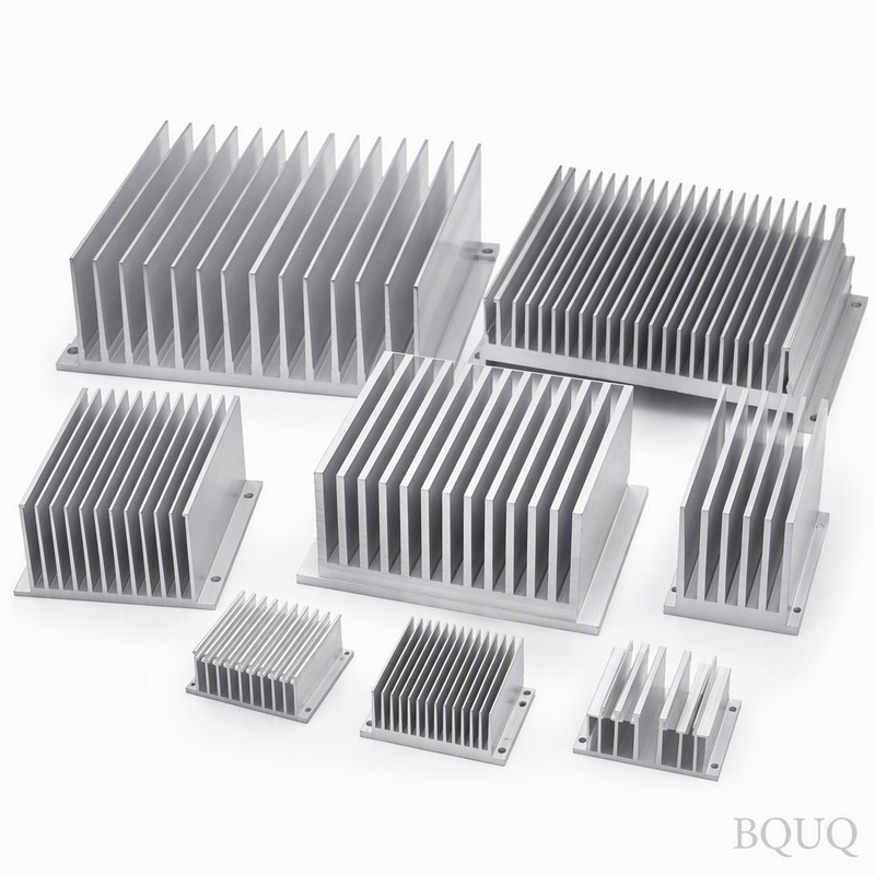
For extruded aluminum heat sinks with parallel fins, airflow direction is the single most critical factor determining thermal resistance, with a 40-60% performance difference between optimal and poor orientation. When airflow runs parallel to the fin channels, a typical 100mm x 100mm x 40mm heat sink achieves 0.35°C/W thermal resistance at 3 m/s, but the same sink drops to 0.62°C/W when airflow is perpendicular to the fins. Engineers must align forced convection with the fin axis to maximize surface area contact and minimize pressure drop, or redesign the sink geometry for the actual flow vector.
The Physics of Fin Orientation and Boundary Layer Development
Airflow direction dictates the thermal boundary layer thickness along the fin surface. In parallel flow, air travels through the channels between fins, maintaining a thin boundary layer across the entire fin height. At 2 m/s velocity, the convective heat transfer coefficient reaches 45-55 W/m²K for 2mm fin spacing. Perpendicular flow creates a stagnation point at the leading edge, but the boundary layer separates quickly, leaving dead zones behind each fin where heat transfer drops to near-zero.
Experimental data from BQUQ's wind tunnel testing shows that parallel airflow yields a Nusselt number 2.3 times higher than perpendicular flow at identical Reynolds numbers. The pressure drop for parallel flow through a 25mm tall fin array is 35-50 Pa per 100mm of fin length. Perpendicular flow generates 180-250 Pa pressure drop across the same footprint, requiring a significantly more powerful fan that consumes 3-5 times more energy.
Fin Spacing and Airflow Direction Interdependence
Fin spacing must be optimized differently for each airflow direction. For parallel flow, the optimal fin gap ranges from 1.5mm to 3mm depending on air velocity. At 3 m/s, a 2mm gap produces the lowest thermal resistance per unit volume. Reducing the gap to 1mm increases pressure drop by 320% while improving heat transfer by only 12%, making it inefficient for most applications.
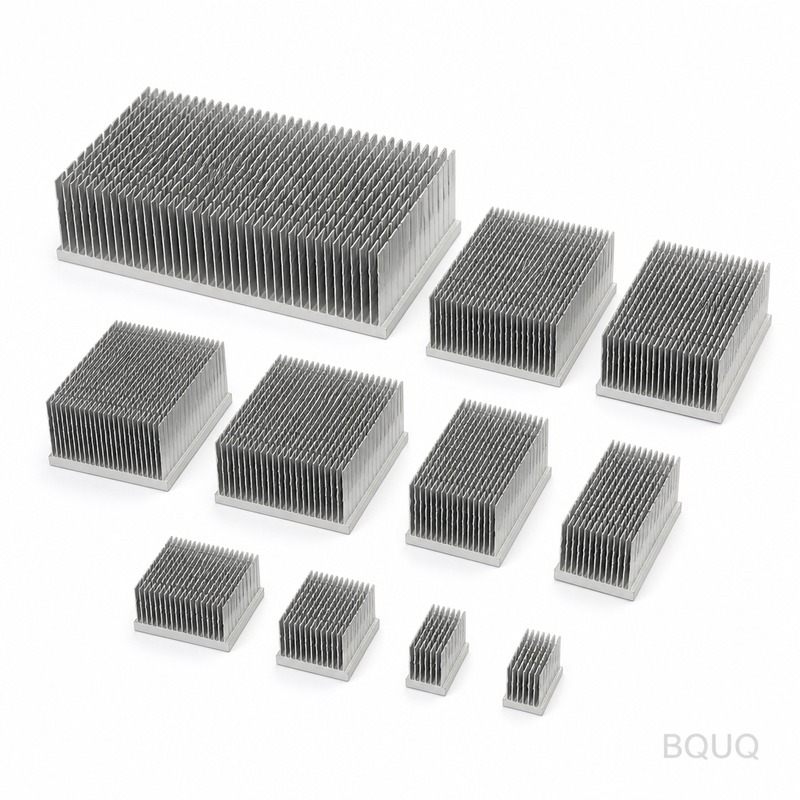
For perpendicular flow, fin spacing becomes less critical because the flow does not penetrate the channels effectively. BQUQ's testing shows that perpendicular flow over 2mm spaced fins provides only 38% of the heat dissipation achieved with parallel flow at the same fan power. If perpendicular flow is unavoidable, engineers should specify pin-fin or skived heat sinks, which have isotropic flow characteristics and only lose 15-20% efficiency in cross-flow orientation.
Thermal Resistance Comparison Under Controlled Testing
BQUQ conducted controlled wind tunnel tests on identical 6063-T5 aluminum heat sinks with a 75mm x 75mm base and 40mm fin height. The heat sink was mounted on a 50W ceramic heater, and thermal resistance was measured at steady state with inlet air at 25°C. The test matrix varied airflow direction, velocity, and fin density.
| Airflow Direction | Velocity (m/s) | Fin Gap (mm) | Thermal Resistance (°C/W) | Pressure Drop (Pa) | Base Temp (°C) |
| Parallel to fins | 1.5 | 2.0 | 0.48 | 18 | 49.0 |
| Parallel to fins | 3.0 | 2.0 | 0.35 | 42 | 42.5 |
| Parallel to fins | 3.0 | 3.0 | 0.38 | 28 | 44.0 |
| Perpendicular to fins | 1.5 | 2.0 | 0.78 | 95 | 64.0 |
| Perpendicular to fins | 3.0 | 2.0 | 0.62 | 210 | 56.0 |
| Perpendicular to fins | 3.0 | 3.0 | 0.58 | 160 | 54.0 |
| 45-degree angle | 3.0 | 2.0 | 0.44 | 68 | 47.0 |
The data confirms that a 45-degree airflow angle performs nearly as well as parallel flow, with only a 25% degradation in thermal resistance. This is because the flow vector still has a significant component along the fin channels, maintaining partial boundary layer disruption.
Shrouding and Bypass Effects on Real-World Performance
In actual electronic enclosures, airflow direction is often compromised by bypass paths around the heat sink. When a heat sink is placed in a duct that is 20% larger than the sink footprint, up to 40% of the airflow bypasses the fins entirely. This reduces effective velocity through the fin channels, increasing thermal resistance by 25-35%.
BQUQ recommends a shroud with a maximum clearance of 1-2mm on each side of the heat sink to force air through the fin channels. For parallel flow systems, a tapered inlet shroud that transitions from the fan diameter to the heat sink width recovers 15% more pressure at the fin entrance. In perpendicular flow installations, a turning vane or air guide can redirect flow into the parallel direction with only a 5-8 Pa pressure penalty.
Fan Placement and Flow Field Interaction
The distance between the fan and the heat sink entrance significantly affects the effective airflow direction. A fan positioned within 10mm of the heat sink creates a concentrated jet that spreads into a non-uniform velocity profile. BQUQ measurements show that the center 60% of the fin area receives 80% of the airflow, leaving the outer fins starved and creating hot spots with temperature differences of 8-12°C across the base.
Placing the fan 25-40mm upstream allows the flow to develop a more uniform profile, reducing the temperature gradient to 3-5°C. For axial fans, the swirl component causes airflow to enter the fins at an angle of 10-15 degrees. This slight angle is beneficial as it promotes turbulence without significant pressure loss. For centrifugal blowers, the exit flow is inherently perpendicular to the fin axis unless a scroll housing or diffuser is used to turn the flow.
Practical Engineering Recommendations
For new designs, always orient the heat sink fins parallel to the dominant airflow path. If the system has multiple fans or natural convection, use a pin-fin heat sink design that is less sensitive to direction. For retrofits where the airflow direction is fixed, consider adding a flow straightener or perforated plate to align the flow before it reaches the heat sink.
BQUQ's manufacturing data shows that a custom extruded aluminum heat sink with optimized fin spacing costs between $8 and $25 per unit for quantities of 500-2000 pieces, with tooling costs of $800-$1500. Skived heat sinks range from $15 to $40 per unit but offer 20-30% better performance in perpendicular flow. For high-volume production above 5000 units, extruded sinks with a secondary CNC machining operation to modify the inlet edge can achieve the best cost-to-performance ratio.
The inlet fin edge geometry matters: a 0.5mm radius on the leading edge of each fin reduces pressure drop by 12% and improves heat transfer by 6% at 3 m/s. This is achieved without any additional manufacturing cost when included in the extrusion die design. Chamfered fin tips at a 15-degree angle provide a similar benefit for perpendicular flow applications.
Conclusion
Airflow direction is not a secondary consideration but a first-order design parameter that can make or break a thermal management system. Parallel flow delivers 40-60% better heat sink performance than perpendicular flow, and the penalty for misalignment increases with air velocity and fin density. Engineers should verify the actual flow vector in their enclosure early in the design phase, using CFD simulation or prototype testing with a simple anemometer array. When in doubt, choose a pin-fin geometry that tolerates multi-directional flow, or add a shroud and flow straightener to enforce the correct direction. BQUQ's 20 years of CNC machining and heat sink manufacturing experience confirms that most thermal failures trace back to airflow misalignment rather than insufficient surface area.
For your next heat sink project, BQUQ provides free airflow direction analysis and thermal simulation with every quotation. Our engineering team responds within 12 hours with a complete thermal assessment, including fin spacing optimization for your specific airflow conditions. Contact us at sc@bquq.com or WhatsApp +86 13713157787, or visit www.bquq.com to upload your CAD files and thermal requirements for immediate evaluation.


