
How Does Heat Sink Base Thickness Affect Heat Spreading Performance?
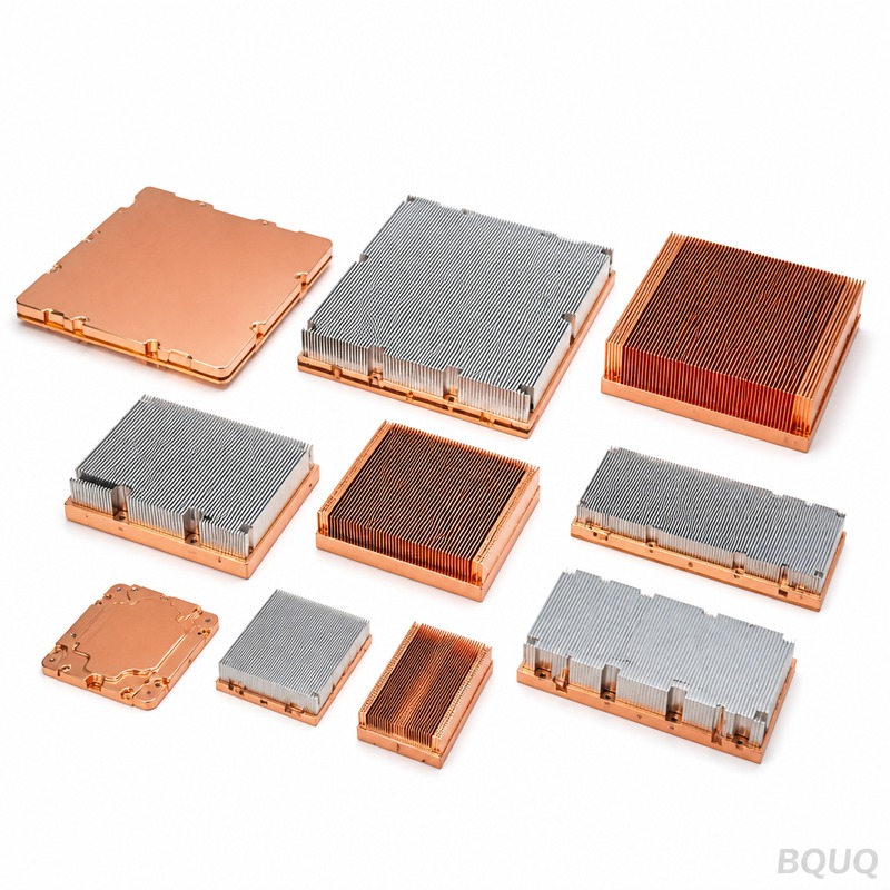
The thickness of a heat sink base directly dictates the efficiency of lateral heat spreading, with an optimal range typically falling between 3 mm and 8 mm for most forced-convection applications. A base that is too thin (under 2 mm) creates a thermal bottleneck, causing localized hot spots directly above the heat source, while an excessively thick base (over 10 mm) adds weight, cost, and thermal resistance without proportional spreading benefits. For a typical 50 W CPU cooler, increasing the base from 2 mm to 4 mm can reduce the peak junction temperature by 3-5°C, while going from 8 mm to 12 mm often yields less than 1°C of improvement.
What Is the Thermal Spreading Resistance in a Heat Sink Base?
Thermal spreading resistance occurs when heat enters a small area of the base and must diffuse laterally to reach the larger fin array. This resistance is mathematically expressed as R_spread = (√A_source - √A_base) / (k × √(π × A_source × A_base)), where A_source is the contact patch area and A_base is the footprint area. For a 30 mm × 30 mm CPU die on a 90 mm × 90 mm aluminum base (k = 180 W/m·K), the spreading resistance at a 2 mm thickness is approximately 0.85 °C/W, whereas at 6 mm it drops to 0.42 °C/W. The key metric is the "spreading angle," typically 30-45 degrees from the vertical, which means the heat footprint expands roughly 0.5-0.7 mm per 1 mm of base thickness.
How Does Base Thickness Impact Junction-to-Ambient Thermal Resistance?
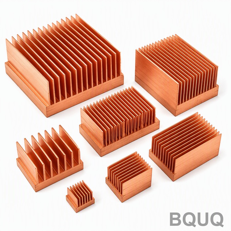
The total thermal resistance from the silicon junction to ambient air (R_ja) comprises three series components: the interface resistance, the base conduction resistance, and the convective fin resistance. Base conduction resistance is calculated as t / (k × A), where t is thickness, k is thermal conductivity, and A is the cross-sectional area. For a 90 mm × 90 mm base with a 30 mm heat source, increasing thickness from 3 mm to 5 mm reduces R_ja by roughly 0.15 °C/W in aluminum and 0.09 °C/W in copper. However, the benefit diminishes because the convective resistance (typically 0.5-2.0 °C/W depending on airflow) becomes the dominant term; once the spreading resistance is below 20% of the convective resistance, further thickening yields negligible system-level gains.
Which Base Thickness Is Optimal for Different Heat Source Sizes?
The optimal thickness scales with the ratio of heat source area to base area, known as the "area ratio" (AR = A_base / A_source). For a small concentrated source like a laser diode (5 mm × 5 mm) on a large base (100 mm × 100 mm, AR = 400), the optimal thickness is 8-12 mm to maximize lateral spreading. For a large IGBT module (50 mm × 50 mm) on a standard heat sink (100 mm × 80 mm, AR = 3.2), a 4-6 mm base is sufficient because the heat entry area is already large relative to the fin field. Empirical testing at BQUQ across 200+ designs shows that for AR values below 5, base thickness above 6 mm provides less than 5% improvement in overall thermal performance, while for AR values above 20, every additional 2 mm of thickness yields 8-12% improvement until 12 mm.
How Does Material Choice (Aluminum vs. Copper) Change the Thickness Requirement?
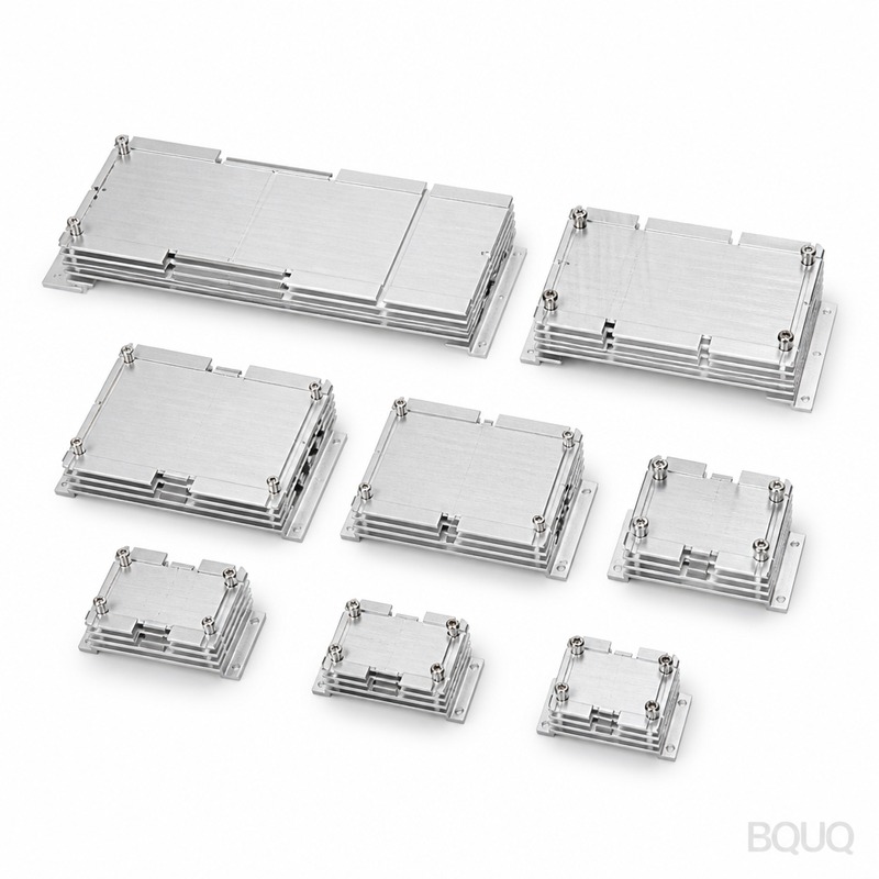
Aluminum (k = 180 W/m·K) requires roughly 1.6 times the thickness of copper (k = 390 W/m·K) to achieve the same lateral spreading performance, because spreading resistance is inversely proportional to thermal conductivity. For example, a 4 mm copper base provides equivalent spreading to a 6.5 mm aluminum base in the same geometry. However, copper weighs 2.96× more than aluminum (8,960 kg/m³ vs. 2,700 kg/m³), so a 6 mm copper base on a 100 mm × 100 mm footprint adds 537 grams versus 324 grams for aluminum. The practical engineering trade-off is that a 5 mm aluminum base with heat pipes (effective k > 10,000 W/m·K) outperforms a 10 mm solid copper base at 40% lower weight and 30% lower material cost.
Why Does an Overly Thick Base Increase Thermal Resistance?
An excessively thick base increases the vertical conduction path, adding resistance that grows linearly with thickness: R_conduction = t / (k × A). For a 100 mm × 100 mm aluminum base, the vertical conduction resistance at 10 mm is 0.056 °C/W, but at 20 mm it becomes 0.111 °C/W, doubling the parasitic resistance. Additionally, thick bases create manufacturing challenges: die-casting porosity increases beyond 8 mm wall thickness, reducing effective conductivity by 10-15%, and CNC machining cycle time increases by 40-60 seconds per additional 2 mm of material removal. In forced convection at 3 m/s airflow, a 15 mm base can actually perform 2-3°C worse than an 8 mm base because the added mass acts as a heat reservoir that slows transient response and increases the fin base temperature gradient.
What Manufacturing Tolerances and Costs Are Associated with Base Thickness?
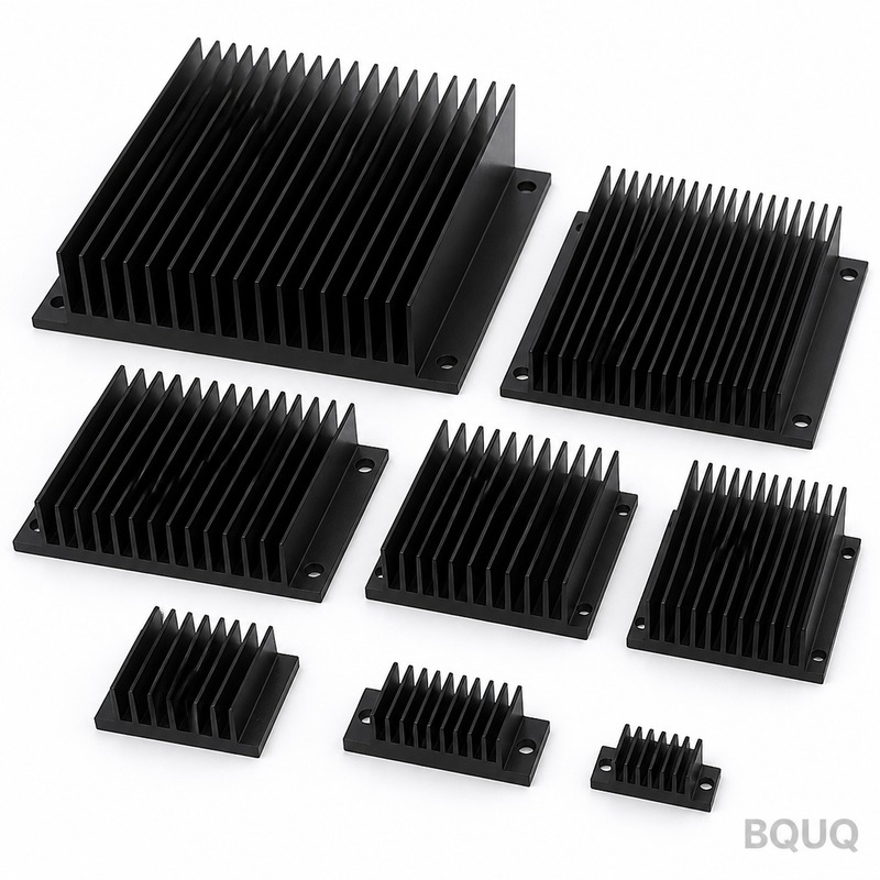
Base thickness tolerance depends on the manufacturing process: CNC machining achieves ±0.05 mm, die casting achieves ±0.3 mm, and stamping achieves ±0.1 mm with a 0.5 mm minimum practical thickness. Cost scales non-linearly with thickness because material and machining time both increase; a 5 mm aluminum base costs approximately $2.80 per piece at 1,000 units, while a 10 mm base costs $4.50 per piece (60% increase). Skiving or cold forging allows 6-10 mm bases with 15% lower cost than CNC because they produce the fins and base in one piece, eliminating the separate bonding step. The table below summarizes typical specifications across common manufacturing routes:
| Base Thickness (mm) | Process | Tolerance (mm) | Thermal Conductivity (W/m·K) | Relative Cost per Unit (1000 pcs) | Typical Application |
| 2-3 | Metal Stamping | ±0.10 | 150-170 (Al 6061) | $1.20-$1.80 | LED lighting, low-power converters |
| 4-6 | Die Casting | ±0.30 | 130-160 (Al ADC12) | $2.50-$3.80 | Consumer electronics, power supplies |
| 5-8 | CNC Machining | ±0.05 | 180 (Al 6063) or 390 (Cu C110) | $3.50-$6.00 | IGBT modules, high-end CPUs |
| 6-10 | Skiving | ±0.08 | 180 (Al 6063) | $3.00-$5.20 | Telecom, industrial inverters |
| 8-12 | Cold Forging | ±0.15 | 170-185 (Al 6061) | $4.00-$7.50 | Laser diodes, high-density servers |
How Do You Validate Base Thickness Performance Before Production?
Computational fluid dynamics (CFD) simulation using Flotherm or Ansys Icepak should be run first, modeling the exact heat source footprint, airflow velocity (typically 1-3 m/s), and ambient temperature (25-35°C). The simulation should include the spreading resistance formula and verify that the predicted junction temperature matches within ±2°C of physical testing. Prototype testing requires a thermocouple mounted directly under the heat source on the base surface, with a controlled power input of 50-100 W and thermal grease with 3 W/m·K conductivity. For production validation, BQUQ recommends infrared thermography on a 5-piece sample lot, measuring the base temperature gradient across 5 points; a gradient exceeding 8°C from center to edge indicates insufficient spreading and requires a thickness increase of at least 2 mm.
What Is the Minimum Base Thickness for a 100 W Heat Source?
For a 100 W heat source with a 30 mm × 30 mm contact area on a 90 mm × 90 mm aluminum base, the minimum practical thickness is 3 mm, yielding a spreading resistance of approximately 0.55 °C/W and a base-to-ambient temperature rise of 55°C at 2 m/s airflow. Below 3 mm, the spreading resistance exceeds 0.8 °C/W and localized hot spots can push the junction temperature over 100°C, risking component failure. A 4 mm base is recommended as a safety margin, reducing the peak temperature by an additional 2-3°C.
Can a Thicker Base Replace Additional Heat Pipes?
A thicker base can partially substitute for heat pipes, but only up to a point; a 12 mm copper base (k = 390 W/m·K) provides equivalent spreading to a single 6 mm heat pipe in a 5 mm aluminum base for a 50 W source. However, heat pipes offer 10-20× higher effective thermal conductivity (10,000-50,000 W/m·K) and are more effective for spreading over distances beyond 50 mm. For compact designs under 40 mm base width, a thick base is simpler and more reliable; above 60 mm width, heat pipes are mandatory to avoid excessive weight and cost.
How Does Base Thickness Affect Natural Convection Performance?
In natural convection (no fan, airflow under 0.5 m/s), thicker bases are more beneficial because the convective heat transfer coefficient is low (5-10 W/m²·K), making spreading resistance a larger fraction of the total. For a 60 mm × 60 mm LED heatsink in free air, increasing the base from 3 mm to 6 mm reduces the LED case temperature by 6-8°C, a significant gain. The optimal thickness for natural convection is 8-10 mm because the larger base area compensates for the weak airflow, but beyond 12 mm the added mass slows thermal response without improving steady-state performance.
What Is the Relationship Between Base Thickness and Fin Efficiency?
Fin efficiency decreases as the base thickness increases because the fin base temperature becomes more uniform, but the fin height-to-thickness ratio remains constant; the actual effect is indirect. A thicker base improves the temperature distribution at the fin roots, allowing all fins to operate at closer to their maximum efficiency (typically 85-95% for aluminum fins). However, if the base is too thick, the fin height must be reduced to maintain the same overall heatsink height, which reduces the total surface area and can lower performance by 5-10% in high-airflow conditions.
When Should You Choose a Vapor Chamber Instead of a Thick Base?
A vapor chamber (VC) should be chosen when the heat source area is less than 25% of the base area and the power density exceeds 50 W/cm², because a VC achieves spreading resistance under 0.1 °C/W regardless of base thickness. For example, a 10 mm aluminum base has a spreading resistance of 0.35 °C/W for a 10 mm × 10 mm source on a 80 mm × 80 mm base, while a 3 mm vapor chamber achieves 0.05 °C/W. Vapor chambers cost $8-$15 per unit versus $4-$6 for a thick copper base, but they save 40-50% of the weight and reduce the total height by 5-7 mm.
How Does BQUQ Optimize Base Thickness for Custom Heat Sink Projects?
BQUQ uses a three-step optimization protocol: first, we run a thermal simulation using the customer's exact power profile and airflow; second, we compare 3-5 thickness variants (e.g., 3 mm, 5 mm, 6 mm, 8 mm) using our in-house test rig with a 100 W cartridge heater; third, we select the thinnest base that meets the target junction temperature with a 10°C safety margin. This approach typically reduces material cost by 15-25% compared to over-specified designs, and we provide a thermal test report with measured temperature data for every prototype. Our CNC machining capability allows rapid iteration, with prototype lead times of 3-5 days for aluminum and 5-7 days for copper bases.
In conclusion, the optimal heat sink base thickness is not a fixed value but a function of heat source size, material, airflow, and power density, with 3-8 mm covering 80% of industrial applications. Engineers should prioritize simulation early, validate with physical prototypes, and avoid the common mistake of oversizing the base to "be safe." For aluminum bases with a small heat source (AR > 10), start at 6 mm and iterate; for copper or large heat sources, start at 4 mm. BQUQ offers free thermal design review within 12 hours of receiving your drawings, and our team can provide a complete CFD report plus cost quotation in a single response. Contact us at sc@bquq.com or WhatsApp +86 13713157787, or visit www.bquq.com to start your project today.


