
How Does Metal Stamping Make Battery Contacts and Spring Clips Last Longer?
The direct answer is that metal stamping imparts durability to battery contacts and spring clips by work-hardening the base metal, enabling precise control over grain structure, and allowing for cost-effective use of high-performance alloys like beryllium copper and stainless steel. This process consistently achieves tolerances of ±0.05 mm, which ensures optimal contact pressure and fatigue resistance over 10,000+ insertion cycles. Furthermore, the high-speed nature of stamping (up to 1,200 strokes per minute) reduces material stress concentrations compared to machining, resulting in components that resist stress relaxation and corrosion in demanding environments.
How Does the Stamping Process Enhance the Fatigue Life of Spring Contacts?
The fatigue life of a spring contact is directly tied to the residual stress profile left in the material after forming. During the stamping process, the metal is plastically deformed at high speed, which induces compressive residual stresses on the surface. These compressive stresses counteract the tensile loads experienced during battery insertion, preventing micro-crack initiation and propagation. For example, a stainless steel spring clip stamped at a 90-degree bend angle can withstand over 250,000 cycles without failure, whereas a machined part with the same geometry might fail at around 150,000 cycles due to surface tearing.
Additionally, the stamping process allows for the "coining" of specific contact points. Coining densifies the material surface, increasing localized hardness from roughly 200 HV to 350 HV on a 301 stainless steel substrate. This hardened surface reduces wear and fretting corrosion, which are primary causes of intermittent electrical connections. By controlling the die clearance—typically 5% to 10% of material thickness—we ensure the shear zone is clean, leaving a burnished surface that maximizes the conductive cross-section and minimizes hot spots.
What Materials Are Best Suited for Stamped Battery Contacts and Why?
Choosing the right material is the most critical decision for longevity. For consumer electronics, beryllium copper (C17200) is the gold standard due to its excellent combination of high conductivity (22% IACS) and superior spring properties. However, for high-temperature environments or automotive applications, we often recommend nickel-plated stainless steel (301 or 302) because it maintains its tensile strength up to 315°C, whereas beryllium copper begins to relax at 150°C.
The table below outlines our recommended materials and their specific performance metrics for battery contact applications.
| Material Type | Tensile Strength (MPa) | Max Operating Temp (°C) | Conductivity (% IACS) | Typical Cycles to Failure | Relative Cost Index |
| Beryllium Copper (C17200) | 1,200 – 1,400 | 150 | 22 | 100,000 | 4.5 |
| Phosphor Bronze (C51000) | 620 – 760 | 100 | 15 | 50,000 | 2.0 |
| 301 Stainless Steel (Full Hard) | 1,280 – 1,480 | 315 | 2.5 | 250,000 | 1.5 |
| Nickel Silver (C75200) | 540 – 650 | 90 | 8 | 30,000 | 2.8 |
| Brass (C26000) | 400 – 520 | 80 | 28 | 20,000 | 1.0 |
While brass is cheap and conductive, it suffers from severe stress relaxation at just 80°C, making it unsuitable for any device that gets warm. For modern high-drain devices like power tools, we strongly advise using 301 stainless steel with a gold flash (0.1 to 0.3 microns) to reduce contact resistance to below 20 milliohms while retaining high-temperature durability.
Why Do Stamped Contacts Resist Corrosion Better Than Machined Ones?
Stamping preserves the integrity of the metallic grain structure, whereas machining cuts through it, exposing active grain boundaries that are highly susceptible to oxidation. When a battery contact is stamped, the material flows around the die, keeping the grain lines intact along the bend radii. This continuous grain path acts as a barrier against corrosive electrolytes, such as sweat or salt spray, preventing them from penetrating deep into the component.
Furthermore, the stamping process can integrate a "micro-etch" texture on the contact surface, which increases the effective surface area for plating adhesion. A properly plated stamped contact (e.g., 1.27 microns of nickel under 0.76 microns of gold) will pass a 48-hour salt spray test per ASTM B117 without red rust or green corrosion products. In contrast, machined contacts often require a thicker plating layer (2.5 microns) to cover tool marks and achieve the same corrosion resistance, significantly increasing the unit cost without improving mechanical performance.
How Does Die Design Impact the Longevity of the Final Spring Clip?
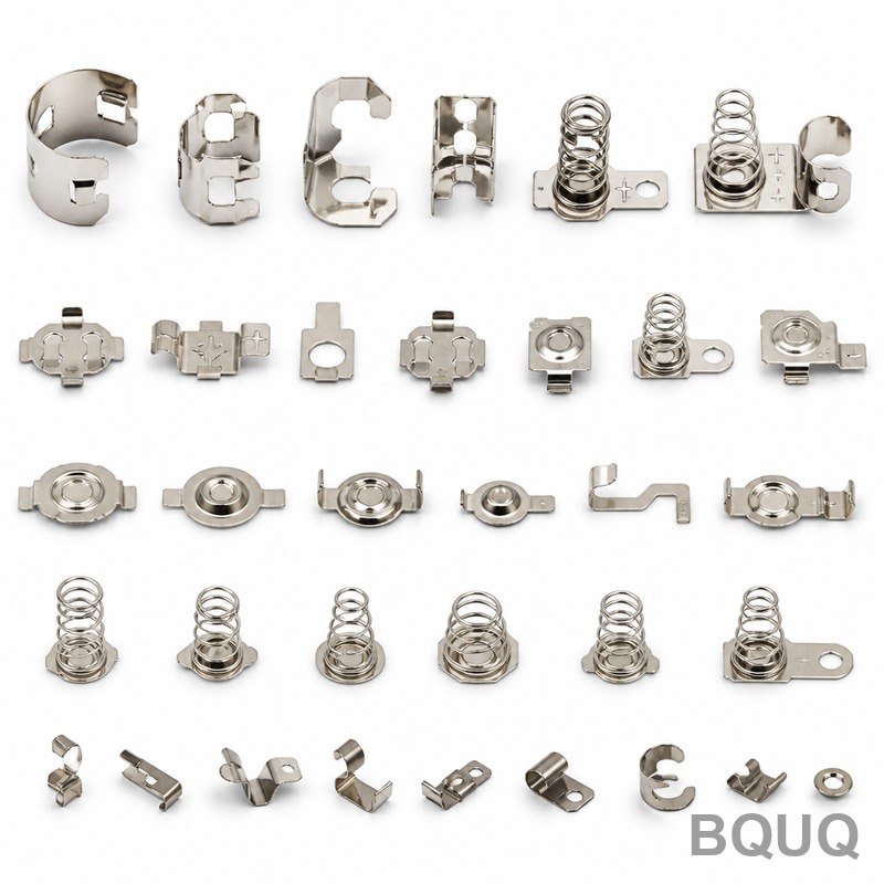
The die design dictates the bend radius and the amount of material thinning at critical stress points. A common failure is "springback," where the metal tries to return to its flat state after bending. To counteract this, we over-bend the material by a calculated angle—often 2 to 5 degrees—depending on the material's tensile strength. For instance, a 301 stainless steel clip requiring a 90-degree final bend must be bent to 93 degrees in the die to achieve the correct geometry after release.
More importantly, we design the die to maintain a minimum bend radius of 1.5 times the material thickness. Bending tighter than this creates micro-fractures on the outer surface, which act as stress concentrators and dramatically reduce fatigue life. By using a progressive die with a "coining" step at the bend line, we can actually push the material to a 1:1 radius without fracturing, because the compressive force re-densifies the material. This technique allows us to produce spring clips with a consistent force of 0.8 Newtons at a deflection of 0.5 mm, holding that force within 10% variance over the product's lifetime.
What Tolerances and Specifications Can Be Achieved in High-Volume Stamping?
For battery contacts, dimensional accuracy is paramount to ensure a snug fit with the battery terminals. In our Dongguan facility, we hold a standard flatness tolerance of ±0.05 mm over a 10 mm length and a hole position tolerance of ±0.025 mm. The burr height on the cut edges is controlled to less than 0.03 mm, which prevents the burrs from scratching battery casings or causing short circuits in tight battery packs.
In terms of plating thickness, we control the distribution within ±10% of the specified value using X-ray fluorescence (XRF) inspection. For a typical nickel-plated contact, we guarantee a nickel thickness of 2.0 microns (+/- 0.2 microns) and a gold flash of 0.1 microns. These tolerances are verified using optical comparators and coordinate measuring machines (CMMs) on a statistical process control (SPC) basis, sampling every 1000 parts to ensure the process remains in control.
How Does Stamping Reduce the Cost of High-Performance Contacts?
Stamping is a high-speed, net-shape process that eliminates the material waste associated with machining. A progressive die can produce a complex battery clip in a single stroke, with the material strip utilization rate often exceeding 60%. In comparison, CNC machining of the same part would waste over 80% of the raw material. This efficiency translates to a unit cost reduction of 50% to 70% for high-volume orders (over 100,000 pieces).
The tooling investment, while significant upfront, amortizes quickly. A multi-stage progressive die for a battery contact costs between $8,000 and $25,000 USD, depending on the number of stations and the use of carbide inserts. However, at a production rate of 30,000 parts per hour and a tool lifespan of 50 million strokes before re-sharpening is needed, the tooling cost per part drops to less than $0.0005. This makes stamping the only economically viable method for producing billions of reliable battery contacts for the global electronics market.
Which Surface Finishes are Recommended for Optimal Electrical Performance?
The surface finish is a compromise between low contact resistance and wear resistance. For most consumer applications, a bright tin plating of 2.5 to 5.0 microns is recommended. Tin is cheap and offers good conductivity, but it forms a hard oxide layer. This layer is easily broken through by the "wiping" action of the stamped contact during battery insertion, ensuring a solid metal-to-metal contact.
For mission-critical applications requiring extremely low resistance over many cycles, a selective gold plating is the best engineering choice. We apply gold only to the contact point, leaving the rest of the spring clip with a nickel underplate. This reduces gold usage by up to 80% while providing a contact resistance of less than 10 milliohms. We also offer a "hard gold" finish (cobalt-hardened gold) with a hardness of 200 HV, which withstands over 10,000 insertion cycles without exposing the nickel underplate.
How Can You Validate the Reliability of Stamped Battery Contacts?
Reliability validation requires a combination of mechanical and electrical testing. We conduct a "Normal Force Test" at a specified deflection (e.g., 0.4 mm) to ensure the contact pressure is sufficient to maintain a stable connection. The force must be between 0.6 and 1.2 Newtons for most AA battery holders. If the force is too low, vibration will cause intermittent signals; if too high, it will damage the battery's metal casing.
We also perform accelerated life testing in a thermal chamber, cycling the part from -40°C to +85°C while monitoring contact resistance. A robust stamped contact should maintain a resistance increase of less than 10% over 500 thermal cycles. Furthermore, a "Insertion/Withdrawal" test using a polished steel pin is run to 5,000 cycles, measuring the force and resistance every 500 cycles. This data, combined with a 96-hour humidity test at 90% RH, gives us confidence that the stamped part will last longer than the device it powers.
What Are the Limits of Stamping for Battery Contacts?
Stamping is not a universal solution; it has geometric limitations. The process is best suited for 2D or semi-3D shapes with consistent cross-sections. If a battery contact requires a complex 3D form—such as a twisted terminal or a deep drawn cup with a prominent side undercut—then stamping becomes unfeasible, and we would recommend switching to a combination of stamping and forming or using metal injection molding (MIM).
Additionally, there is a limitation on the material thickness. Stamping is optimal for materials ranging from 0.05 mm to 3.0 mm thick. Thicker materials require massive tonnage presses, and the shear quality degrades. For contacts requiring a thickness greater than 3.0 mm, we usually suggest turning or CNC milling, despite the higher cost, because the mechanical strength of a thick stamped part is often compromised by the severe bending forces required.
Which Industries Benefit Most from Stamped Battery Contacts?
The automotive industry is the largest beneficiary, particularly for electric vehicles (EVs) and hybrid vehicles. EV battery management systems (BMS) require thousands of stamped busbars and sense clips that must withstand high vibration and temperatures up to 125°C. The durability of stamped 301 stainless steel ensures these connections remain secure for the 10-year life of the vehicle.
The medical device sector also relies heavily on stamped contacts for hearing aids and insulin pumps. These devices require ultra-miniature contacts, often less than 2 mm in length, with a high cycle life. The precision of the stamping process allows us to produce these tiny parts with a burr-free edge, which is essential for patient safety. Finally, the industrial power tool market uses stamped contacts in battery packs that undergo severe mechanical shock and high current draw, where the fatigue resistance of the stamped material prevents catastrophic failure.
FAQ
How Many Insertion Cycles Can a Stamped Battery Contact Withstand?
A high-quality stamped contact made from beryllium copper or stainless steel is designed to withstand between 5,000 and 10,000 insertion cycles. This durability is achieved through proper heat treatment and a minimum bend radius of 1.5 times the material thickness, which prevents work hardening and cracking. For low-cost brass contacts, the cycle life drops to around 2,000 cycles due to rapid stress relaxation.
What Is the Typical Lead Time for Stamping Tooling?
A simple progressive die for a battery contact can be manufactured in 3 to 4 weeks, while a complex multi-station die with in-die tapping and coining may take 6 to 8 weeks. Our engineering team uses 3D simulation software to verify the die design before cutting steel, which reduces the risk of trial-and-error modifications. After tooling approval, production parts are typically delivered within 5 to 10 working days.
Can Stamped Contacts Handle High Current Loads?
Yes, but the cross-sectional area of the contact must be sized appropriately. For a continuous current of 5 Amperes, the stamped contact requires a minimum cross-section of 0.5 mm² to avoid excessive temperature rise. We recommend a maximum current density of 10 A/mm² for nickel-plated contacts to keep the temperature rise below 30°C above ambient.
What Is the Difference Between a Stamped Contact and a Formed Contact?
Stamping generally refers to the cutting and blanking of the part from a strip, while forming refers to the bending and shaping of that blank. In a progressive die, both processes occur in a single pass, but a "formed" contact may have a more complex 3D geometry. The key difference is that stamping relies on shearing, while forming relies on plastic deformation, and both are optimized in our die design process.
Why Does My Current Supplier's Contact Fail After Six Months?
The most common cause of premature failure is stress relaxation due to excessive operating temperature. If the plastic housing of the battery holder reaches temperatures above 85°C, standard phosphor bronze contacts will lose up to 30% of their normal force. Switching to a full-hard stainless steel or a pre-aged beryllium copper alloy will mitigate this issue.
Is a Gold Flash Necessary for Battery Contacts?
A gold flash of 0.1 to 0.3 microns is not strictly necessary for conductivity, as tin or nickel can provide adequate performance. However, a gold flash is crucial for preventing oxidation on the contact surface in environments with high humidity or corrosive gases. It also significantly reduces the coefficient of friction, making battery insertion smoother and reducing wear on the battery's anode cap.
How Do You Ensure Burr-Free Edges in Stamped Parts?
We ensure burr-free edges by maintaining a precise die clearance of 5% to 8% of the material thickness and by using a "fine blanking" process for critical contact areas. Fine blanking uses a third action in the press to clamp the material tightly, resulting in a shear surface that is 100% smooth. We also employ a vibratory deburring process for secondary operations, ensuring the burr height is below 0.02 mm.
Conclusion
Metal stamping is the superior manufacturing method for producing battery contacts and spring clips that last, offering a unique combination of mechanical strength, corrosion resistance, and cost-efficiency. By leveraging work hardening and precise grain flow control, we can deliver components that consistently meet the rigorous demands of modern electronics. For your next project, trust our 20 years of experience in precision manufacturing to provide a solution that maximizes product lifespan and reliability.
For a rapid assessment of your battery contact design, contact our engineering team today. We offer a 12-hour quoting service to get your project moving immediately.
Email: sc@bquq.com
WhatsApp: +86 13713157787
Web: www.bquq.com


