
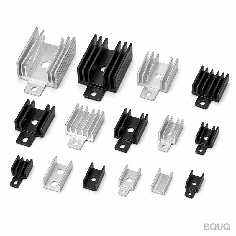
How to Calculate Heat Sink Size for Your Application
To calculate heat sink size, you must first determine the total thermal resistance required between the component junction and the ambient air, then divide the maximum allowable temperature rise by the power dissipation. This calculation yields a required thermal resistance value (in °C/W) that you match against a heat sink’s performance curve or datasheet. For a 10 W processor with a 50 °C allowable temperature rise above ambient, you need a heat sink with a thermal resistance of 5.0 °C/W or lower, which typically translates to an extruded aluminum profile of roughly 75 mm x 75 mm x 25 mm with natural convection.
What Is the Basic Formula for Heat Sink Sizing?
The governing equation is a simple thermal circuit analogy: Tj = Ta + (P x Rth), where Tj is junction temperature, Ta is ambient temperature, P is power dissipation in watts, and Rth is the total thermal resistance from junction to ambient. To find the maximum allowable total thermal resistance, rearrange the formula to Rth(max) = (Tj(max) - Ta) / P. This total resistance is the sum of three series resistances: junction-to-case (Rth-jc), case-to-sink (Rth-cs), and sink-to-ambient (Rth-sa). For most calculations, you will solve for Rth-sa, the heat sink’s own thermal resistance, which is the only value you can control through geometry and material.
As a practical example, consider a MOSFET producing 15 W of heat with a maximum junction temperature of 150 °C and an ambient temperature of 50 °C. The allowable temperature rise is 100 °C, giving a total Rth of 6.67 °C/W. If the junction-to-case resistance is 0.5 °C/W and the case-to-sink interface (with thermal paste) is 0.2 °C/W, the required sink-to-ambient resistance is 5.97 °C/W. You would then select a heat sink with a datasheet value of 6.0 °C/W or lower under your specific airflow conditions.
How Do You Convert Thermal Resistance to Physical Dimensions?
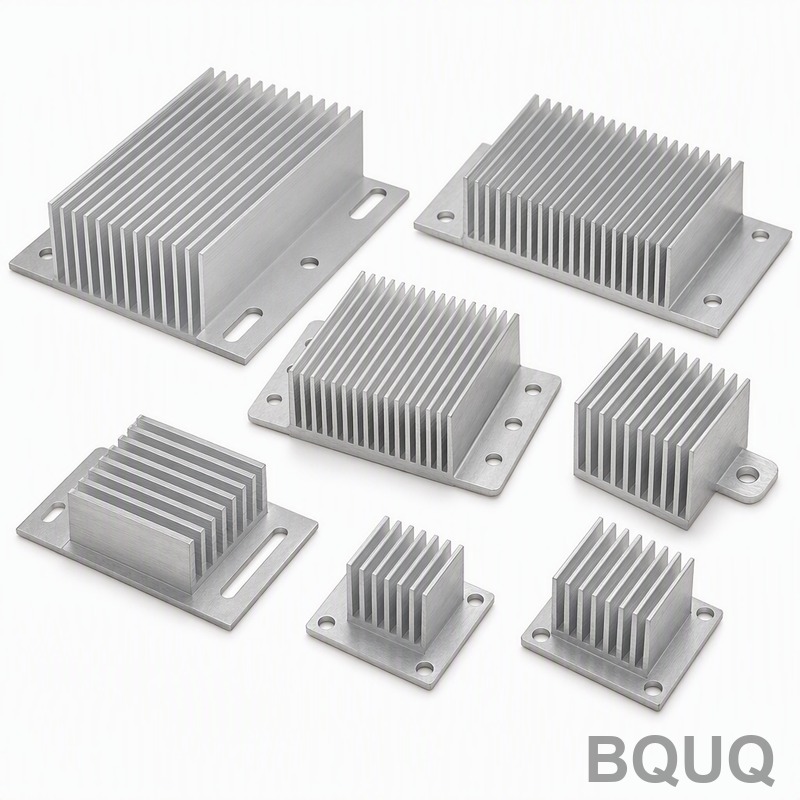
For natural convection with extruded aluminum heat sinks, a useful rule of thumb is that a 1 °C/W thermal resistance requires approximately 100 to 150 square centimeters of surface area. For forced convection with airflow of 2 m/s, the required surface area drops to roughly 40 to 60 square centimeters per 1 °C/W. From these area targets, you can derive length, width, and fin height. A 5 °C/W natural convection heat sink, for example, needs about 500 to 750 cm² of total wetted surface area, which could be achieved with a 100 mm x 100 mm base plate and 12 fins of 20 mm height.
Extruded profiles typically have fin heights between 10 mm and 40 mm, fin thicknesses between 1.5 mm and 3.0 mm, and fin pitch (center-to-center spacing) between 5 mm and 10 mm. For natural convection, wider fin spacing of 7 to 10 mm is preferred to reduce boundary layer interference. For forced convection, tighter spacing of 4 to 6 mm increases surface area per unit volume. The base plate thickness should be at least 5 mm for even heat spreading, though 8 to 10 mm is recommended for heat sources larger than 25 mm in diameter.
Why Does Ambient Temperature and Altitude Matter in the Calculation?
Ambient temperature directly reduces the available temperature difference between the heat sink surface and the surrounding air, which is the driving force for heat dissipation. If your ambient temperature is 70 °C instead of 25 °C, the allowable temperature rise for a 125 °C junction limit drops from 100 °C to 55 °C, meaning you need roughly double the surface area for the same power. At higher altitudes, air density decreases, reducing the convective heat transfer coefficient by approximately 2 to 3 percent per 300 meters of elevation gain. At 3000 meters altitude, you may need 20 to 30 percent more surface area compared to sea level for the same performance.
For natural convection, the heat transfer coefficient is typically between 5 and 15 W/(m²·K) depending on orientation and fin geometry. For forced convection, the coefficient ranges from 20 to 100 W/(m²·K) depending on air velocity. Most thermal simulations and datasheet values assume sea level conditions with air at 20 to 25 °C. Always derate your heat sink performance by 10 percent for every 15 °C above 25 °C ambient, and by 10 percent for every 1000 meters above sea level.
Which Material Should You Choose for Your Heat Sink?
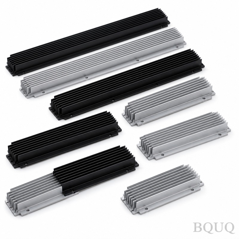
Aluminum 6063-T5 is the industry standard for extruded heat sinks, offering a thermal conductivity of approximately 200 W/(m·K) at a cost of USD 3 to 6 per kilogram. Copper provides 385 W/(m·K) but costs USD 8 to 15 per kilogram and weighs 3.3 times more, so it is typically used only when space is extremely constrained. Aluminum 6061-T6 is slightly stronger but has the same thermal conductivity, while ADC12 die-cast aluminum has a lower conductivity of about 96 W/(m·K) due to porosity and alloy content, making it less efficient despite lower tooling costs.
For high-volume applications, aluminum extrusion tooling costs between USD 800 and USD 3000 per profile, with lead times of 2 to 4 weeks. Die-cast heat sinks require tooling of USD 10,000 to USD 50,000 but offer more complex shapes. Stamped aluminum fin assemblies, common in BQUQ’s production line, offer thermal performance within 10 to 15 percent of solid extrusions at a lower unit cost for volumes above 10,000 pieces per year. Skived copper heat sinks provide conductivity close to pure copper at 380 W/(m·K) but cost 30 to 50 percent more than extruded aluminum.
How Much Surface Area Do You Need for a Given Power Dissipation?
The following table provides empirical surface area requirements for natural convection aluminum heat sinks at sea level with a 30 °C temperature rise above ambient. These values assume a black anodized surface, which improves emissivity from 0.1 (bare aluminum) to 0.9, enhancing radiative heat transfer by 20 to 30 percent.
| Power Dissipation (W) | Required Surface Area (cm²) | Typical Heat Sink Size (mm) | Estimated Rth-sa (°C/W) |
| 5 | 200 | 60 x 60 x 15 | 6.0 |
| 10 | 350 | 75 x 75 x 25 | 5.0 |
| 15 | 500 | 100 x 100 x 25 | 4.0 |
| 20 | 650 | 120 x 120 x 30 | 3.0 |
| 30 | 950 | 150 x 150 x 35 | 2.5 |
| 50 | 1600 | 200 x 200 x 40 | 1.8 |
| 75 | 2400 | 250 x 250 x 45 | 1.2 |
For forced convection at 2 m/s airflow, divide the required surface area by 2.5 to 3.0. For 5 m/s airflow, divide by 4.0 to 5.0. These multipliers assume the airflow is directed along the fin channels with minimal blockage. If your application has restricted airflow or the heat sink is enclosed in a housing, increase the surface area by 50 percent.
How Do You Account for Contact Resistance and Thermal Interface Materials?
The interface between the heat source and the heat sink base contributes 0.1 to 1.0 °C/W depending on surface flatness, pressure, and the thermal interface material (TIM) used. A 0.1 mm layer of thermal grease with a conductivity of 1.5 W/(m·K) on a 25 mm x 25 mm die yields approximately 0.1 °C/W. Phase-change materials and thermal pads range from 1.0 to 5.0 W/(m·K) but add 0.2 to 0.5 °C/W due to their thickness. For best performance, use a 25 µm to 50 µm layer of thermal grease applied evenly, with a mounting pressure of 10 to 30 psi.
Surface flatness of the heat sink base should be 0.05 mm or better for optimal contact. BQUQ machines heat sink bases to a flatness tolerance of 0.02 mm over 100 mm length, ensuring minimal interface resistance. If you must mount multiple heat sources on one sink, spread them at least 10 mm apart and use a base thickness of at least 8 mm to avoid thermal coupling. For high-power IGBT modules, consider vapor chamber or heat pipe heat sinks, which can reduce spreading resistance by 50 percent compared to solid aluminum.
When Should You Consider Active Cooling Instead of a Larger Heat Sink?
If your required Rth-sa is below 1.0 °C/W and the heat sink volume exceeds 500 cm³, forced convection with a fan is usually more cost-effective than a passive heat sink. A 40 mm x 40 mm fan providing 10 m³/h of airflow at 3000 RPM can reduce the required surface area by 60 percent, lowering the heat sink volume from 500 cm³ to 200 cm³. Fans add 1 to 5 W of power consumption and a mean time between failures of 30,000 to 70,000 hours, which may be acceptable for industrial equipment but not for sealed consumer electronics.
For power densities above 50 W/cm² on the heat source, consider liquid cooling, which achieves 0.05 to 0.2 °C/W with a cold plate and radiator. Heat pipes are effective for moving heat from a confined source to a remote fin stack, with a typical capacity of 50 to 100 W per pipe. The decision criterion is simple: if the heat sink volume required for passive cooling exceeds 1 liter, or the weight exceeds 2 kilograms, active cooling or heat pipes will reduce total system cost and space.
What Are the Practical Steps to Validate Your Heat Sink Size?
First, calculate the required Rth-sa using the formula in Section 1, including all interface resistances. Second, estimate the surface area using the table in Section 4, then select a standard extrusion profile that provides at least that area. Third, measure the actual thermal resistance using a thermocouple on the heat source and a second thermocouple in the ambient air, with a known power load. Fourth, adjust for orientation: horizontal fins perform 10 to 15 percent worse than vertical fins in natural convection due to reduced chimney effect.
Use a CFD simulation tool or empirical testing to verify fin efficiency, which typically ranges from 70 to 90 percent for aluminum fins. If your measured temperature rise exceeds the calculated value by more than 15 percent, check for poor contact, insufficient mounting pressure, or blocked airflow. For production validation, BQUQ recommends a thermal cycle test of 1000 cycles from -40 °C to 125 °C to ensure the TIM does not pump out and the heat sink does not warp.
FAQ
What Is a Reasonable Thermal Resistance for a Small Heat Sink?
A 50 mm x 50 mm x 10 mm aluminum heat sink with natural convection provides approximately 8 to 10 °C/W. For comparison, a 100 mm x 100 mm x 25 mm sink provides 3 to 4 °C/W, and a 200 mm x 200 mm x 40 mm sink provides 1.2 to 1.8 °C/W.
How Does Anodizing Improve Heat Sink Performance?
Black anodizing increases the surface emissivity from 0.1 to 0.9, which improves radiative heat transfer by 20 to 30 percent in natural convection. The anodic layer is electrically insulating and corrosion-resistant, adding no measurable thermal resistance when applied at 10 to 25 µm thickness.
Can I Use a Heat Sink Without Thermal Paste?
You can, but the interface resistance will increase from 0.1 °C/W to 0.5 to 1.0 °C/W due to air gaps, which have a thermal conductivity of only 0.026 W/(m·K). This can reduce effective heat sink performance by 30 to 50 percent, so thermal paste or a pad is strongly recommended.
What Is the Maximum Fin Height for an Extruded Heat Sink?
Standard aluminum extrusions can achieve fin heights up to 75 mm with a fin thickness of 1.5 mm and a height-to-width ratio of 1:50. For taller fins above 75 mm, use skiving, bonding, or brazed fin assemblies, which can reach 150 mm heights.
How Do I Calculate Heat Sink Size for Pulsed Power Loads?
For pulsed loads, average the power over the thermal time constant of the heat sink, which is typically 1 to 5 minutes for aluminum extrusions. If the pulse duration is under 10 seconds, use the thermal capacitance of the heat sink to absorb the energy spike without exceeding the junction temperature.
What Airflow Rate Is Needed for a Forced Convection Heat Sink?
A minimum of 1 to 2 m/s of airflow across the fin channels is required to achieve a 2.5x improvement over natural convection. For a 100 mm x 100 mm heat sink, this corresponds to 0.6 to 1.2 m³/min of airflow from a fan.
How Much Does a Custom Heat Sink Cost?
An extruded aluminum heat sink with custom tooling costs USD 800 to 3000 for the die, plus USD 3 to 6 per kilogram for the material. Machining adds USD 10 to 50 per piece depending on features, and anodizing adds USD 1 to 3 per square meter.
BQUQ’s engineering team can calculate the exact heat sink size for your application within 12 hours. Send your power dissipation, ambient temperature, and maximum junction temperature to sc@bquq.com or reach us on WhatsApp at +86 13713157787. Visit www.bquq.com for datasheets and standard profiles.


