How to Calculate Stamping Force: Engineering Guide with Formulas and Tolerances
How to Calculate Stamping Force: Engineering Guide with Formulas and Tolerances
**The direct answer:** Stamping force is calculated using the formula **F = L × t × S** (where F is force in kilonewtons, L is the total shear length in millimeters, t is material thickness in millimeters, and S is the material's shear strength in megapascals). For a typical 2 mm thick stainless steel part with a 300 mm perimeter, the required force is approximately 300 × 2 × 520 = 312 kN (31.8 metric tons). This calculation must be increased by 20-30% for press selection to account for stripping force, friction, and dynamic variations.
---
1. The Basic Stamping Force Formula: Breaking Down Each Variable
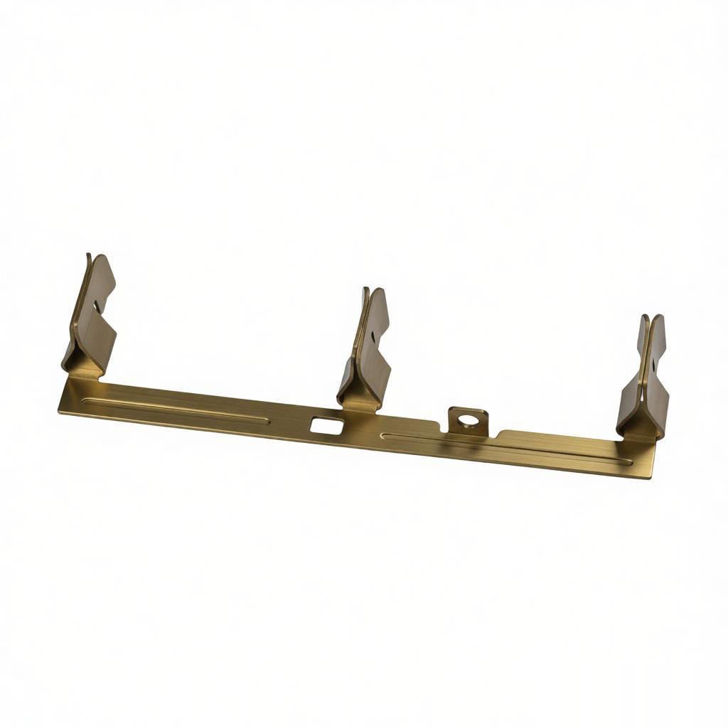
The fundamental equation for stamping force in a blanking or piercing operation is:
**F = L × t × S**
| Variable | Symbol | Unit | Typical Value Range | ---------- | -------- | ------ | --------------------- | Cutting force | F | kN | 50 – 5,000 kN | Shear length | L | mm | 10 – 2,000 mm | Material thickness | t | mm | 0.1 – 6.0 mm | Shear strength | S | MPa | 180 – 620 MPa |
|---|
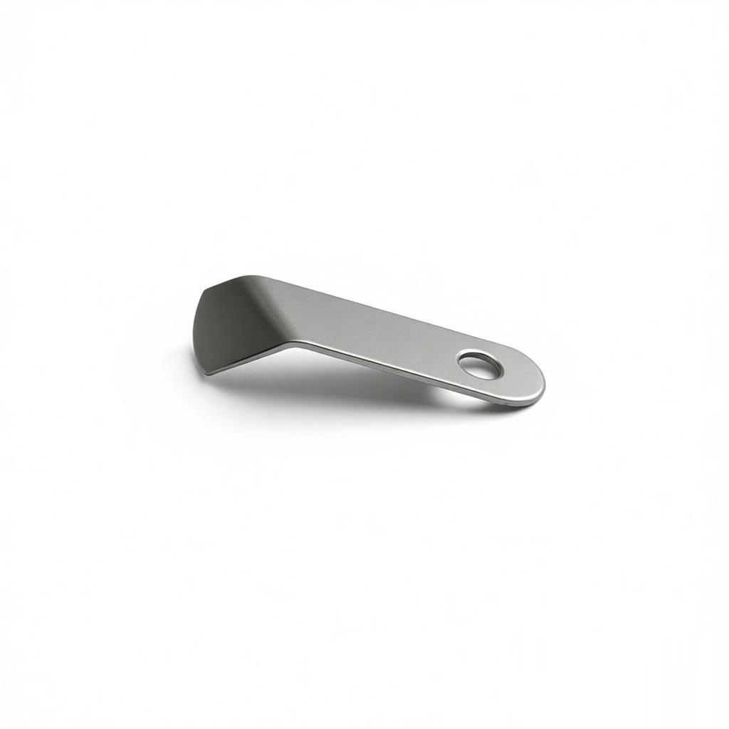
**How to determine each variable:**
- **L (Shear length):** For blanking, this is the perimeter of the blank. For piercing, it is the circumference of the hole. For multiple holes, sum all perimeters. - **t (Thickness):** Nominal stock thickness. For tight tolerances, use the maximum thickness per ASTM or JIS spec (e.g., for 2.0 mm cold-rolled steel, actual thickness may be 2.05 mm). - **S (Shear strength):** Approximately 70-80% of tensile strength. For cold-rolled steel (SPCC), S ≈ 300 MPa. For stainless steel 304, S ≈ 520 MPa. For aluminum 5052, S ≈ 180 MPa.
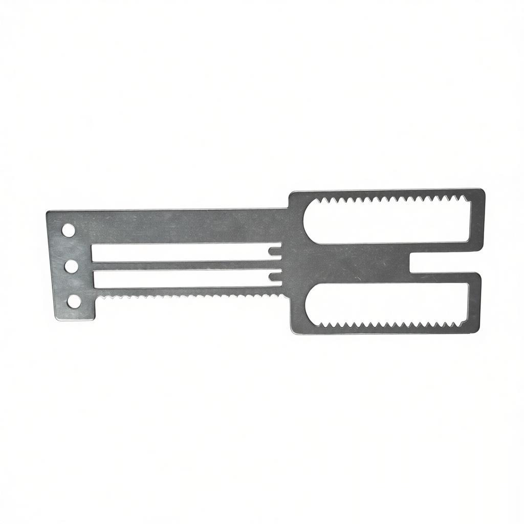
**Worked Example:** Part: Rectangular bracket, 100 mm × 50 mm, 2 mm thick SPCC steel. L = 2 × (100 + 50) = 300 mm F = 300 × 2 × 300 = 180,000 N = 180 kN ≈ 18.3 metric tons
**Add 20% safety factor:** Required press capacity = 216 kN → select a 25-ton press.
---
2. Advanced Considerations: Stripping Force, Bending Force, and Coining Pressure
The basic formula covers cutting, but real stamping operations include additional force components.
### Stripping Force (Fs) The force required to strip the material from the punch after piercing. Typically 10-20% of the cutting force.
**Fs = 0.15 × F** (for most steels with standard clearance)
### Bending Force (Fb) — V-Die Formula For V-bending, use: **Fb = (k × L × t² × TS) / V** Where: - k = 1.33 for V-die - L = bending length (mm) - t = thickness (mm) - TS = tensile strength (MPa) - V = die opening width (mm), typically 8× t
**Example:** 100 mm bend, 2 mm steel (TS=400 MPa), V=16 mm Fb = (1.33 × 100 × 4 × 400) / 16 = 13,300 N = 13.3 kN
### Coining Pressure If coining (full thickness embossing), pressure = 5-8 × the material yield strength over the coined area. A 10 mm² coining area on hardened steel requires up to 50 kN.
---
3. Real-World Data: Stamping Force Table for Common Materials
Below is a reference table from our BQUQ factory data (20 years of CNC and stamping production records):
| Material Grade | Thickness (mm) | Shear Strength (MPa) | Force per 100 mm Perimeter (kN) | Recommended Press Tonnage (ton) | Typical Tolerance Achievable (±mm) | ---------------- | ---------------- | ---------------------- | -------------------------------- | --------------------------------- | ----------------------------------- | SPCC (cold-rolled steel) | 1.0 | 300 | 30 | 5 | 0.05 | SPCC (cold-rolled steel) | 2.0 | 300 | 60 | 10 | 0.05 | SPCC (cold-rolled steel) | 3.2 | 300 | 96 | 16 | 0.08 | SUS304 (stainless) | 1.5 | 520 | 78 | 13 | 0.05 | SUS304 (stainless) | 2.0 | 520 | 104 | 18 | 0.05 | SUS304 (stainless) | 3.0 | 520 | 156 | 26 | 0.08 | AL5052 (aluminum) | 1.5 | 180 | 27 | 5 | 0.08 | AL5052 (aluminum) | 3.0 | 180 | 54 | 9 | 0.10 | C1100 (copper) | 2.0 | 240 | 48 | 8 | 0.05 | SK5 (spring steel) | 1.0 | 600 | 60 | 10 | 0.03 |
|---|
**Note:** Press tonnage values include a 20% safety margin. Tolerances assume a precision die with proper clearance (5-8% of thickness per side for steel).
---
4. Die Clearance and Its Effect on Force and Part Quality
Die clearance directly impacts required force and edge quality.
**Optimal clearance (per side) = 5% × t** for steel, **8% × t** for aluminum, **6% × t** for stainless steel.
**Effect on force:** - Clearance too tight (2-3%): Force increases by 15-25%, causes excessive die wear and burr. - Clearance too large (10%+): Force decreases by 10%, but produces rollover and poor edge finish.
**Temperature effect:** At high stamping speeds (>100 strokes/min), friction raises die temperature to 60-80°C. This can reduce effective shear strength by 5-10%. For high-speed stamping of 0.5 mm steel, recalculate force using S × 0.95.
**Our factory standard:** For SPCC 2.0 mm, we use 0.10 mm clearance per side. This yields a clean shear zone (about 30% of thickness) and a burnish zone (70%), maintaining flatness within 0.1 mm over 200 mm length.
---
5. Press Selection: Why You Need 20-30% More Than Calculated Force
Never select a press rated exactly at the calculated force. Reasons:
1. **Dynamic load spikes:** During impact, actual force can exceed static calculation by 10-15%. 2. **Die wear:** As punches dull, force increases by up to 20%. 3. **Material variation:** Real-world sheet thickness and hardness vary by ±5% from spec. 4. **Stripping force:** Additional 10-20% on top of cutting force.
**Selection formula:** Press capacity ≥ F_calculated × 1.25
**Example:** A 312 kN stamping job requires a press rated at 390 kN minimum. Standard press sizes: 40 ton (400 kN) or 50 ton (500 kN). Choose the 50-ton press for longevity.
**Cost implication:** A 40-ton press costs roughly USD 15,000-25,000; a 50-ton press costs USD 20,000-35,000 (2025 market prices for C-frame presses). The 25% extra capacity extends die life by 30-40%, justifying the initial cost.
---
6. Practical Recommendations from BQUQ Engineering
**For prototypes and low-volume runs (1-100 pieces):** - Use progressive die with calculated force, but verify with a tryout on a hydraulic press at 80% of rated capacity. - Measure actual force using a load cell installed on the punch holder. Compare with theoretical value; adjust clearance if deviation exceeds 8%.
**For high-volume production (10,000+ pieces):** - Add a force monitoring system (strain gauge on press frame). Alert if force exceeds 110% of baseline — indicates die wear or material change. - Schedule die sharpening when burr height exceeds 0.05 mm for steel or 0.08 mm for aluminum.
**Material substitution:** - If switching from SPCC to SUS304 at same thickness, force increases by 73% (300 → 520 MPa). Recalculate press capacity before making the change.
**Lubrication:** - Use low-viscosity stamping oil (ISO VG 10-15) for thin materials (<1.5 mm). This reduces friction by 15-20%, lowering effective force and improving edge quality. - For stainless steel, use chlorinated extreme-pressure oil to prevent galling.
---
FAQ-Style Tips for Common Stamping Force Problems
**Q: My calculated force is 200 kN, but the press stalls at 180 kN. What went wrong?** A: Check actual material thickness — 2.0 mm spec may be 2.1 mm actual. Recalculate with 2.1 mm: force increases to 210 kN. Also verify shear strength: if using HR (hot-rolled) steel instead of CR (cold-rolled), strength may be 10% higher.
**Q: How do I reduce stamping force without changing material?** A: Use angled punch (shear angle of 3-5 degrees). This reduces peak force by 30-40% but increases stroke length. For a 2 mm steel part, a 5-degree shear angle reduces force from 312 kN to about 200 kN.
**Q: What is the minimum tonnage for piercing a 5 mm hole in 3 mm stainless?** A: L = π × 5 = 15.7 mm; F = 15.7 × 3 × 520 = 24.5 kN. With safety factor, require 30 kN. A 5-ton press is sufficient, but ensure frame rigidity to maintain hole position tolerance within ±0.03 mm.
**Q: Does stamping speed affect force?** A: Yes. At 200 strokes/min, dynamic effects can increase peak force by 10%. For high-speed stamping, use a press with 30% oversizing and a heavier flywheel.
---
Conclusion: Precision Stamping Force Calculation is Your Cost-Saving Lever
Accurately calculating stamping force prevents three costly failures: press overloading (machine damage and downtime), die breakage (tooling cost of USD 2,000-10,000 per die), and part quality defects (scrap rate increase from 1% to 5%). The formula F = L × t × S, adjusted with a 25% safety factor, is the industry baseline. Always verify with actual material certificates and conduct a tryout before full production.
At BQUQ, we have applied these calculations across 20 years of stamping production — from 0.2 mm precision shims to 6 mm structural brackets. Our engineering team will recalculate your stamping force, verify die clearance, and recommend the optimal press configuration at no charge.
**Get a 12-hour quote:** Send your 2D/3D drawings to **sc@bquq.com** or WhatsApp **+86 13713157787**. Visit **www.bquq.com** for our full CNC machining, metal stamping, spring, and heat sink capabilities. We will return your stamping force calculation and cost estimate within one business day.
Related Articles
- Design for Stamping: 7 Blanking Layout Rules to Cut Scrap Cost by 18% in 2025
- 5 Effective Burr Removal Techniques for Stamped Parts
- 5 Proven Ways to Reduce Cost in Metal Stamping Parts
Frequently Asked Questions
What is the formula for calculating stamping force?
The stamping force is calculated using F = L × t × S, where F is force in kilonewtons, L is the total shear length in millimeters, t is material thickness in millimeters, and S is the material's shear strength in megapascals. For example, a 2 mm thick stainless steel part with a 300 mm perimeter requires approximately 312 kN (31.8 metric tons).
How much safety factor should I add when selecting a press?
You should increase the calculated stamping force by 20-30% for press selection. This accounts for stripping force, friction, and dynamic variations. For instance, a 180 kN calculated force becomes 216 kN with a 20% safety factor, leading to selection of a 25-ton press.
What are typical shear strength values for common materials?
Shear strength is approximately 70-80% of tensile strength. For cold-rolled steel (SPCC), S ≈ 300 MPa. For stainless steel 304, S ≈ 520 MPa. For aluminum 5052, S ≈ 180 MPa. These values are used in the stamping force formula F = L × t × S.
How do I calculate stripping force and bending force?
Stripping force is typically 10-20% of cutting force, calculated as Fs = 0.15 × F for most steels. Bending force for V-die uses Fb = (k × L × t² × TS) / V, where k = 1.33, V is die opening width (typically 8× t). For a 100 mm bend in 2 mm steel with TS=400 MPa and V=16 mm, Fb = 13.3 kN.