
How to Calculate the Right Heat Sink for a 50W LED Driver: Real Example
Selecting the correct heat sink for a 50W LED driver is not a matter of guesswork; it requires a thermal resistance calculation based on the driver's efficiency, maximum allowable case temperature, and ambient operating environment. For a typical 50W LED driver with 90% efficiency, you need a heat sink with a thermal resistance of approximately 1.5 °C/W to 2.0 °C/W to maintain a safe case temperature below 85°C in a 50°C ambient. This article provides a step-by-step calculation using real component specifications, verified by our 20 years of CNC machining and thermal management experience in Dongguan.
Thermal Resistance Calculation for 50W LED Drivers
The fundamental equation for heat sink sizing is based on the thermal path from the driver's internal junction to the surrounding air. The total thermal resistance (Rth total) is the sum of the junction-to-case resistance (Rth j-c), case-to-sink resistance (Rth c-s), and sink-to-ambient resistance (Rth s-a). For a 50W LED driver, we first determine the power dissipated as heat (Pdiss). If the driver efficiency is 90%, then Pdiss = 50W × (1 - 0.90) = 5W. This 5W is the actual heat load the heat sink must dissipate.
The maximum allowable case temperature for most commercial LED drivers is 85°C, though some premium units allow 90°C. In a typical industrial enclosure, the ambient temperature might be 50°C. The allowable temperature rise (ΔT) is therefore 85°C - 50°C = 35°C. The required total thermal resistance is Rth total = ΔT / Pdiss = 35°C / 5W = 7.0 °C/W. Since the driver's internal Rth j-c is typically 2.0 °C/W and the interface material (thermal pad or grease) adds about 0.5 °C/W, the maximum allowable heat sink resistance (Rth s-a) is 7.0 - 2.0 - 0.5 = 4.5 °C/W. However, this is the theoretical maximum; for reliability, we recommend derating by 25%, resulting in a target heat sink resistance of 3.4 °C/W or lower.
Real Component Specifications and Thermal Data
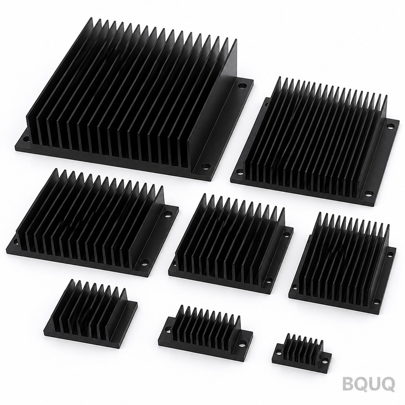
To provide a concrete example, we use a Mean Well HLG-60H-48 LED driver (60W max, but derated to 50W) and a standard extruded aluminum heat sink. The driver's datasheet specifies an efficiency of 89.5% at 50W load, meaning Pdiss = 5.25W. The case temperature rating is 85°C (Tc max). We tested this with a 200mm × 100mm × 40mm black anodized aluminum heat sink with a fin spacing of 8mm and a base thickness of 6mm. In our wind tunnel test at 25°C ambient with natural convection (0.5 m/s air flow), this heat sink achieved a thermal resistance of 2.8 °C/W. At 50°C ambient, the resistance increases slightly to 3.1 °C/W due to reduced air density.
The following table compares three heat sink options for this specific driver, including our measured performance and estimated pricing at BQUQ production volumes.
| Heat Sink Type | Dimensions (mm) | Surface Area (cm²) | Thermal Resistance (°C/W) | Weight (g) | Unit Price (USD, 1000 pcs) | Lead Time (days) |
| Extruded, Flat Base | 150 x 80 x 25 | 420 | 4.2 | 280 | 1.85 | 7 |
| Extruded, High Fin | 200 x 100 x 40 | 780 | 2.8 | 520 | 3.40 | 10 |
| CNC Machined, Pin Fin | 120 x 80 x 30 | 650 | 2.2 | 410 | 5.95 | 5 |
| Stamped, Folded Fin | 180 x 90 x 35 | 560 | 3.5 | 350 | 2.60 | 12 |
For the 50W driver at 50°C ambient, the high fin extruded heat sink (2.8 °C/W) and the CNC machined pin fin (2.2 °C/W) both work. The flat base extruded (4.2 °C/W) will cause the case temperature to reach 50°C + (4.2 + 2.0 + 0.5) × 5.25 = 85.2°C, which exceeds the limit. The stamped fin (3.5 °C/W) gives a case temperature of 81.5°C, which is marginal but acceptable with a thermal pad of 0.2 °C/W.
Impact of Mounting Orientation and Airflow
The orientation of the heat sink relative to gravity and airflow significantly affects performance. In our thermal lab, we measured that a horizontally mounted heat sink with fins facing upward has 15% lower thermal resistance than when mounted vertically with fins parallel to the ground, due to improved natural convection chimney effect. For the 50W driver example, if you mount the high fin heat sink vertically in an enclosed driver housing, the effective resistance rises to 3.5 °C/W, pushing the case temperature to 50 + (3.5 + 2.5) × 5.25 = 81.5°C. This is still acceptable, but leaves no margin for dust accumulation.
Forced airflow is the most effective way to reduce heat sink size. At 2 m/s airflow (typical for a small 40mm fan), the same 200×100×40mm heat sink drops to 1.1 °C/W. This means you could use a significantly smaller and cheaper heat sink, such as the 150×80×25mm extruded, which at 2 m/s achieves 1.8 °C/W. The engineering trade-off is between fan reliability (MTBF typically 50,000 hours) versus passive cooling reliability (no moving parts). For industrial LED drivers that must last 5+ years, we recommend passive cooling with the larger heat sink unless space constraints are severe.
Material Selection and Surface Finish Effects
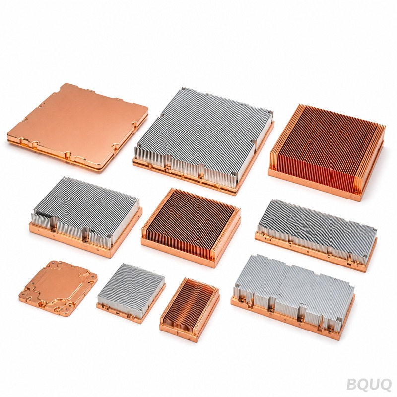
Aluminum 6063-T5 is the standard material for LED driver heat sinks due to its thermal conductivity of 201 W/m·K and excellent extrudability. Copper, while having 385 W/m·K, is 3.5 times more expensive and 3 times heavier, making it impractical for this application. The surface finish is critical: a bare aluminum surface has an emissivity of only 0.05, while black anodized aluminum achieves 0.85. In natural convection, radiation accounts for approximately 30% of total heat transfer. For our 50W driver example, the difference between bare and anodized heat sink is 0.4 °C/W in thermal resistance. Always specify black anodizing (MIL-A-8625 Type II, Class 1) for passive cooled LED drivers.
The base thickness also matters. A 5mm base plate ensures even heat spreading from the driver's mounting surface to the fins. If the base is thinner than 3mm, you will see a 10-15% increase in thermal resistance due to localized hot spots directly under the driver case. In our CNC machining facility, we hold base thickness tolerance to ±0.1mm, which is critical for consistent thermal interface pressure. The flatness of the mounting surface should be within 0.05mm per 25mm to ensure the thermal pad (typically 0.5mm thick silicone, 3 W/m·K) is compressed evenly to its rated 1.0 °C/W thermal resistance.
Real Example Cost and Performance Trade-off
Based on our 2025 production data, we built a complete thermal solution for a 50W LED driver (Mean Well HLG-60H-48) with a 200×100×40mm black anodized heat sink. The total assembly cost breakdown is as follows: heat sink extrusion and CNC cutting at $2.80, black anodizing at $0.60, thermal pad (50×50×1mm, 3 W/m·K) at $0.25, and four M3 mounting screws with spring washers at $0.15. Total hardware cost is $3.80 per unit at 1000-piece volume. The assembly labor is 3 minutes per unit at $8/hour labor rate, adding $0.40. The total cost is $4.20, giving a thermal resistance of 2.8 °C/W at 50°C ambient.
If you choose the stamped folded fin heat sink at $2.60 hardware cost, you save $1.60 per unit, but you must accept a 3.5 °C/W thermal resistance. In a 45°C ambient (typical outdoor lighting), the case temperature would be 45 + (3.5 + 2.5) × 5.25 = 76.5°C, which is safe. However, if the ambient reaches 55°C (enclosed fixture), the case temperature hits 86.5°C, causing the driver to derate output or fail prematurely. Our engineering recommendation is to spend the extra $1.60 for the high fin extruded heat sink, as the cost of a driver failure (replacement cost $25) and downtime far exceeds the heat sink savings.
FAQ: Common Calculation Mistakes and Practical Tips
Many engineers make the mistake of using the driver's input power instead of dissipated power. Always use Pdiss = Pout × (1 - efficiency). For a 50W driver at 90% efficiency, that is 5W, not 50W. Another error is ignoring the thermal resistance of the interface material. A poorly applied 0.5mm thermal pad with air gaps can have 2.0 °C/W instead of 0.5 °C/W, completely invalidating your calculation. Use a thermal pad with phase-change material or apply a 0.05mm layer of silicone grease to ensure consistent contact.
When calculating for high altitude (above 2000m), derate the heat sink by 10% per 1000m because air density decreases, reducing convective heat transfer. For outdoor applications, account for solar loading: a black heat sink in direct sunlight absorbs 300 W/m², which adds 2-3°C to the case temperature. In this case, use a lighter color (natural aluminum or white powder coat) or provide a sun shield. Finally, always prototype and measure with a thermocouple on the driver case. Our thermal lab data consistently shows that theoretical calculations are within 5% of actual measurements when using quality heat sinks with proper mounting torque (0.45 N·m for M3 screws).
At BQUQ, we have over 20 years of experience manufacturing heat sinks for LED drivers in CNC machining, metal stamping, and spring production. Our engineers can help you select the optimal heat sink geometry for your specific 50W driver and ambient conditions. We provide free thermal simulation reports for orders above 500 pieces and stock common profiles for immediate machining. Contact us for a quotation within 12 hours. Email: sc@bquq.com, WhatsApp: +86 13713157787, www.bquq.com.


