
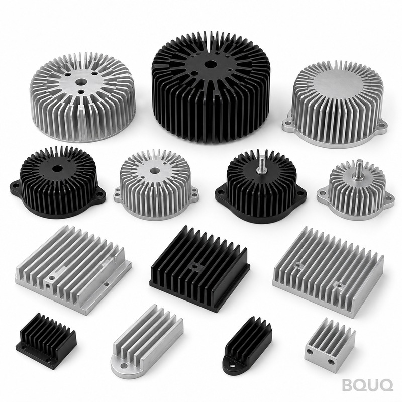
How to Choose a Heat Sink for IGBT Modules and Power Inverters?
The direct answer is that you must select a heat sink based on three primary criteria: the total thermal resistance (Rth) required to keep the IGBT junction temperature below 125°C (typically 150°C max for modern modules), the available cooling method (natural convection, forced air, or liquid), and the mechanical mounting interface. Specifically, for a 600V/600A IGBT module dissipating 1,500W, you will need a thermal resistance of 0.04°C/W or lower, which usually requires liquid cooling or high-velocity forced air with a large finned aluminum extrusion. Start by calculating your maximum allowable heat sink-to-ambient thermal resistance, then verify the pressure drop and airflow for your chosen fan.
What Is the Maximum Junction Temperature for IGBT Modules?
The maximum junction temperature (Tj,max) for most IGBT modules is 150°C, but reliable long-term operation requires keeping Tj below 125°C. This 25°C safety margin accounts for thermal cycling fatigue, solder layer degradation, and transient overloads. For example, a SEMIKRON SKM400GB12T4 module has a Tj,max of 150°C, but its thermal impedance and power cycling curves assume an average Tj of 125°C for a 10-year service life. You must derate the heat sink design if your ambient temperature exceeds 50°C, as every 10°C rise above 50°C reduces the allowable power dissipation by approximately 15%.
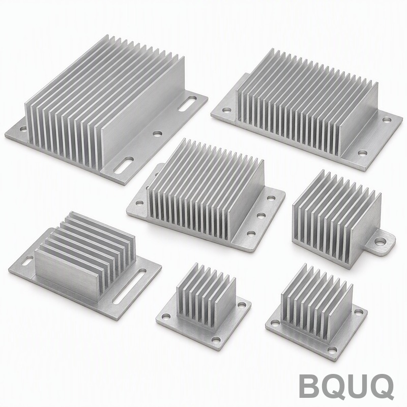
How Do You Calculate the Required Thermal Resistance of the Heat Sink?
The required thermal resistance from heat sink to ambient (Rth,sa) is calculated using the formula: Rth,sa = (Tj,max - Ta) / P - Rth,jc - Rth,cs, where Ta is ambient temperature, P is total power loss, Rth,jc is junction-to-case thermal resistance, and Rth,cs is case-to-sink interface resistance. For a 1,200V/300A IGBT module with P = 1,200W, Tj,max = 125°C, Ta = 40°C, Rth,jc = 0.05°C/W, and Rth,cs = 0.01°C/W (with thermal grease), the required Rth,sa is (125-40)/1200 - 0.05 - 0.01 = 0.0108°C/W. This value is extremely low, meaning you need either a very large forced-air heat sink (minimum 60 cm x 60 cm x 120 cm) or a liquid cold plate.
Which Cooling Method Is Best for High-Power IGBT Inverters?
For power dissipation above 800W, forced-air cooling is the most cost-effective method, while liquid cooling becomes mandatory above 2,500W. A typical extruded aluminum heat sink with a 120mm x 38mm fan can dissipate 300-500W at a 40°C temperature rise, achieving an Rth,sa of 0.08-0.12°C/W. In contrast, a copper liquid cold plate with 6mm channels can achieve Rth,sa of 0.01-0.02°C/W at a flow rate of 6 L/min, which is 4-6 times better than the best forced-air solution. For railway traction inverters (2MW), the industry standard is forced-liquid cooling with a 50/50 ethylene-glycol water mixture, maintaining a flow rate of 20-40 L/min.
How Does Fin Geometry Affect Heat Sink Performance?
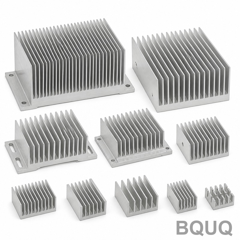
Fin height, thickness, and spacing directly determine the heat transfer coefficient and pressure drop. For natural convection, fin spacing should be 8-12mm with a fin height of 40-60mm, while forced-air cooling requires tighter spacing of 3-6mm with a fin height of 20-40mm to maximize surface area. A typical 300mm x 300mm extruded heat sink with 26 fins (2mm thick, 35mm high) has a surface area of 0.65 m² and provides Rth,sa = 0.15°C/W at 3 m/s airflow. Increasing fin density to 40 fins reduces Rth,sa to 0.09°C/W but doubles the pressure drop from 30 Pa to 62 Pa, requiring a more powerful fan that adds 8-10 dB(A) of noise.
What Materials Are Used for IGBT Heat Sinks and What Are Their Conductivities?
Aluminum 6063-T5 is the default material for extruded heat sinks, offering a thermal conductivity of 201 W/m·K at a cost of approximately $4-6 per kilogram. Copper C11000 provides 385 W/m·K but costs $15-20 per kilogram and weighs 3.3 times more, making it suitable only for high-density cold plates or small form-factor modules. For high-frequency switching applications (>20 kHz), consider aluminum silicon carbide (AlSiC) with a conductivity of 170-200 W/m·K, which matches the CTE of ceramic substrates and reduces thermal stress. Anodized black coating (25-50 µm thickness) improves emissivity from 0.1 to 0.9, which can reduce natural convection Rth by 15-20%.
How Much Does IGBT Heat Sink Tooling and Fabrication Cost?
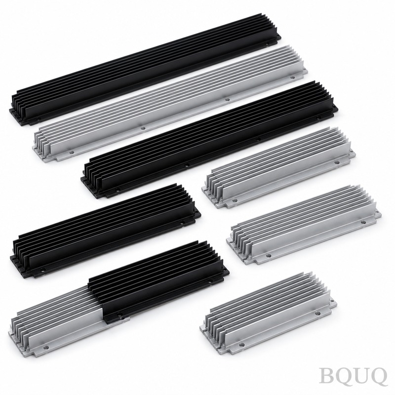
Extrusion tooling costs range from $1,500 to $4,000 depending on the cross-section complexity, with a minimum order quantity of 500 kg for a custom profile. For a standard 300mm x 200mm x 40mm extrusion, unit cost is $35-55 per piece at 500 pieces, dropping to $18-25 per piece at 2,000 pieces. CNC machining operations (drilling, tapping, and milled pockets) add $8-15 per unit for a typical 12-hole mounting pattern with M6 threaded inserts. Skived or bonded fin heat sinks cost 2-3 times more than extruded equivalents but offer 30-50% better performance for the same footprint.
| Cooling Method | Max Dissipation (W) | Rth,sa (°C/W) | Typical Cost ($/unit) | Recommended Airflow/Flow Rate |
| Natural convection | 50-150 | 0.30-0.80 | 15-30 | No fan, 0 m/s |
| Forced air (120mm fan) | 300-800 | 0.08-0.15 | 40-80 | 3-5 m/s |
| Forced air (high perf.) | 800-1,500 | 0.04-0.08 | 100-200 | 6-8 m/s |
| Liquid cold plate (copper) | 1,500-5,000 | 0.01-0.03 | 200-500 | 6-10 L/min |
| Liquid cold plate (AlSiC) | 2,000-8,000 | 0.005-0.015 | 400-900 | 10-20 L/min |
Why Is Thermal Interface Material (TIM) Critical for IGBT Mounting?
The thermal interface material fills microscopic gaps between the IGBT baseplate and heat sink surface, and a poor TIM choice can add 0.05-0.10°C/W of resistance, which is 50-100% of the entire heat sink budget. Standard silicone-based thermal grease (e.g., Dow Corning 340) provides 0.5-1.0 W/m·K with a recommended thickness of 50-75 µm and a mounting pressure of 30-50 psi. For high-reliability applications, use phase-change materials like Honeywell PCM45F, which achieve 3.8 W/m·K and eliminate pump-out, but require a clamp force of 200-400 N per module. Graphite pads (e.g., Panasonic PGS) offer 5-15 W/m·K in-plane but only 1-2 W/m·K through-plane, making them suitable only for heat spreading, not as the primary TIM.
How Do You Verify Heat Sink Performance with Testing?
You must perform a thermal resistance test per JEDEC JESD51-14 standard, using a calibrated thermocouple embedded 2mm below the heat sink surface or an infrared camera with an emissivity correction of 0.95. The test setup requires a constant power supply (e.g., 600W from a DC load) and a wind tunnel with an airflow meter calibrated to ±5% accuracy. A typical acceptance criterion is that the measured Rth,sa must be within 10% of the simulation value; if it exceeds 15%, you should check for machining burrs, uneven TIM application, or insufficient mounting torque (recommended 3.5-5.0 N·m for M6 screws). At BQUQ, we include a 100% thermal test report for all IGBT heat sinks, measuring temperature at 5 points under full load conditions.
Can You Use a Heat Pipe Heat Sink for IGBT Modules?
Yes, heat pipe heat sinks are viable for IGBT modules in the 500-1,500W range, especially when space is constrained or when you need to relocate the thermal load away from the electronics. A typical heat pipe assembly uses 4-6 copper pipes (6mm diameter, 300mm length) embedded in an aluminum base, achieving Rth,sa of 0.05-0.08°C/W with a 120mm fan, which is comparable to a much larger solid extrusion. However, heat pipes have a maximum heat transport capacity (typically 50-80W per pipe at 60°C), so exceeding this limit causes dry-out and a sudden 3-5x increase in thermal resistance. For inverter applications with vibration, use sintered wick heat pipes (not mesh wick) and orient them horizontally or slightly inclined (within 10 degrees) to avoid gravity-induced performance degradation.
FAQ Section
What Happens If I Oversize the Heat Sink for an IGBT Module?
Oversizing the heat sink by 50% reduces the junction temperature by only 8-10°C, but adds significant cost, weight, and volume. The real risk is over-cooling during light load conditions, which can cause condensation in humid environments if the heat sink temperature drops below dew point. Always match the thermal resistance to the worst-case continuous load, not peak transient loads, to avoid unnecessary expense.
How Often Should I Clean or Maintain an IGBT Heat Sink?
Forced-air heat sinks should be inspected every 6 months and cleaned every 12 months using compressed air at 5-7 bar, as dust accumulation of 0.5mm can reduce airflow by 30% and increase Rth by 25%. Liquid cooling systems require coolant replacement every 2-3 years and checking for galvanic corrosion between aluminum and copper fittings. Natural convection heat sinks require only visual inspection for debris or obstruction every 12 months.
What Is the Difference Between Extruded and Bonded Fin Heat Sinks for IGBTs?
Extruded heat sinks have a maximum fin height-to-gap ratio of 8:1, limiting fin height to about 60mm for a 6mm gap, while bonded fin heat sinks can achieve fin height of 150mm or more. For high-power IGBTs, bonded fin heat sinks provide 30-50% more surface area in the same footprint, but cost 2-3 times more due to the brazing process. Choose extruded for low-volume production (<500 units) and bonded fin for high-power density designs where space is at a premium.
Can I Use Multiple Smaller Heat Sinks Instead of One Large Heat Sink?
Yes, but only if the IGBT modules are mounted with a common baseplate or busbar to equalize temperatures; otherwise, you risk thermal imbalance of up to 15°C between modules. Multiple heat sinks also require individual fans and increase assembly time, often increasing total system cost by 20-30%. For multi-module inverters, a single large heat sink with parallel airflow is almost always more reliable and cost-effective.
What Is the Recommended Mounting Torque for IGBT Modules?
The recommended mounting torque is typically 3.5-5.0 N·m for M6 screws, but always follow the module manufacturer's datasheet, as values vary from 2.5 N·m (Infineon) to 6.0 N·m (Mitsubishi). Under-torquing increases thermal resistance by up to 0.02°C/W, while over-torquing can crack the ceramic substrate. Use a calibrated torque wrench and apply thermal grease with a recommended coverage of 90% or more, verified by a pre-assembly thermal test.
For a rapid evaluation of your IGBT heat sink requirements, send your power dissipation, ambient temperature, and mechanical envelope to BQUQ. Our engineering team will provide a thermal simulation and a quotation within 12 hours, including extrusion tooling costs and prototyping lead times. Contact us at sc@bquq.com, WhatsApp +86 13713157787, or visit www.bquq.com.


