
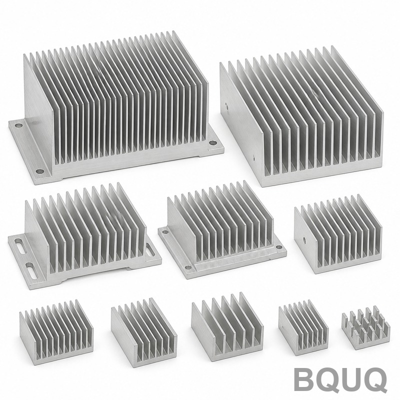
How to Choose a Heat Sink for LED Lighting Applications
Choosing a heat sink for LED lighting requires matching the thermal resistance of the heatsink to the LED junction temperature limit, typically 85°C to 105°C for high-power chips. The decision hinges on four variables: total dissipated power (Watts), allowable ambient temperature, thermal budget (case-to-junction resistance), and the available mounting area. For most commercial LED fixtures above 10W, an extruded aluminum heat sink with a thermal resistance of 0.5°C/W to 2.5°C/W is the standard engineering solution, but stamped steel and bonded fin assemblies offer cost advantages at lower power densities.
Thermal Budget Calculation Method
The engineering starting point is always the junction-to-ambient thermal path. For a typical Cree XHP70.2 or Lumileds LUXEON V, the junction-to-case thermal resistance (Rth j-c) is specified at 0.9°C/W to 1.5°C/W. The thermal interface material (TIM) adds 0.1°C/W to 0.3°C/W depending on whether you use thermal paste, phase-change pad, or graphite film. The heatsink must provide the remaining resistance.
The formula is: Rth hs = (Tj max - Ta max) / P dissipated - Rth j-c - Rth TIM.
Example: A 50W LED module operating at 40°C ambient, with Tj max of 95°C and Rth j-c of 1.2°C/W plus TIM of 0.2°C/W, yields a required heatsink resistance of (95-40)/50 - 1.4 = 1.1°C/W - 1.4 = -0.3°C/W. This negative result indicates active cooling or a larger heatsink is mandatory. For a 20W module, the same calculation gives (55)/20 - 1.4 = 1.35°C/W, which a 200mm x 100mm x 40mm extruded profile with 8 fins can achieve in natural convection.
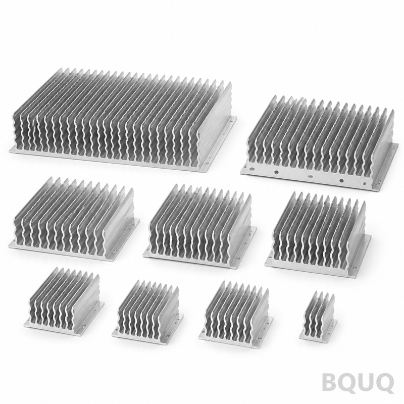
Material Selection: Aluminum 6063-T5 vs ADC12 vs Copper
Extruded aluminum 6063-T5 remains the industry default for LED heatsinks due to its balance of thermal conductivity (201 W/m·K), cost, and extrudability. Die-cast ADC12 (thermal conductivity 96 W/m·K) is cheaper for complex geometries but performs 50% worse thermally, requiring 30% to 40% more surface area for the same dissipation. Copper (385 W/m·K) offers superior performance per volume but costs 4 to 5 times more per kilogram and doubles the weight, making it viable only for compact high-flux applications like automotive headlamps.
For outdoor lighting, the corrosion resistance of 6063-T5 with a clear anodize (8-12 microns) is non-negotiable if the LED driver is potted and the enclosure is IP65. BQUQ's production data shows that for a 30W streetlight module, the cost difference between an extruded 6063-T5 heatsink (CNC-machined mounting face) and a die-cast ADC12 equivalent is only 18% in favor of die-cast, but the thermal performance gap is 35%, often forcing a larger die-cast profile that erases the cost advantage.
Fin Geometry and Surface Area Requirements
Natural convection heatsinks require a fin spacing of 8mm to 12mm to allow airflow without boundary layer interference. Fin height should not exceed 10 times the fin gap; otherwise, the lower fins become thermally inert. For forced convection (fan-cooled), fin spacing can drop to 4mm to 6mm, increasing surface area per volume by 60%. The minimum practical fin thickness for extrusion is 1.2mm; for stamping, 0.8mm is achievable but with a 20% reduction in fin efficiency due to thermal constriction.
A practical rule from BQUQ's thermal lab: for natural convection, you need 40 to 60 square centimeters of exposed surface area per watt of LED power. A 20W LED requires 800 to 1200 cm² of total fin surface. A typical extruded profile measuring 150mm x 100mm x 35mm with 9 fins provides approximately 950 cm² and achieves a thermal resistance of 1.8°C/W at 25°C ambient. For forced convection with a 40mm axial fan delivering 10 CFM, the same profile drops to 0.9°C/W, allowing a 40W LED.
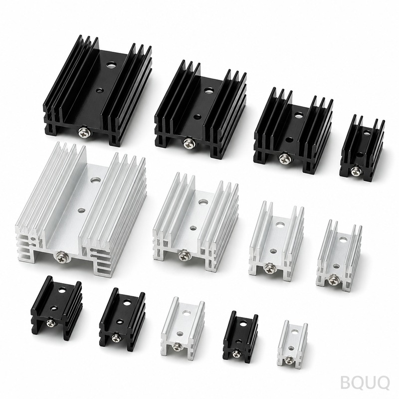
Manufacturing Process Trade-offs: Extrusion vs Stamping vs Bonded Fin
| Process | Thermal Conductivity (W/m·K) | Min Fin Thickness (mm) | Tooling Cost (USD) | Unit Cost at 10k pcs | Lead Time (days) | Best Power Range |
| Extrusion 6063-T5 | 201 | 1.2 | 800-1500 | 2.50 - 6.00 | 7-10 | 10W - 200W |
| Die Casting ADC12 | 96 | 1.5 | 3000-8000 | 3.00 - 5.50 | 15-20 | 5W - 50W |
| Stamped Aluminum 5052 | 138 | 0.8 | 1200-2500 | 1.80 - 3.50 | 5-7 | 1W - 15W |
| Bonded Fin (Al + Epoxy) | 180 (joint limited) | 0.6 | 5000-10000 | 5.00 - 12.00 | 10-14 | 50W - 500W |
| Skived Fin (Copper) | 385 | 0.4 | 8000-15000 | 15.00 - 30.00 | 10-14 | 100W - 1000W |
Stamped aluminum heat sinks are the most common for LED bulbs and downlights under 15W because the tooling is amortized quickly and the thin fins (0.8mm) allow high surface area at low weight. However, stamped fins must be mechanically folded or staked to a base plate, introducing a contact resistance of 0.5°C/W to 1.0°C/W at the interface. For LED arrays above 30W, this interface becomes the bottleneck, and extruded or bonded fin designs are preferred because the mounting face is machined flat to 0.05mm flatness, ensuring minimal TIM thickness.
Mounting Surface, Flatness, and Thermal Interface Material
The mounting surface flatness is as critical as the heatsink material. BQUQ CNC-machines the LED mounting pad to a flatness of 0.05mm over a 50mm length, with a surface roughness of Ra 1.6 micrometers. A warped or stamped surface exceeding 0.1mm flatness will create an air gap that increases thermal resistance by 0.3°C/W to 0.8°C/W, potentially pushing the junction temperature above 120°C and reducing LED lifespan from 50,000 hours to 15,000 hours.
For TIM selection, use thermal grease (0.1°C/W at 25-micron bond line) for permanent assemblies. Phase-change materials (PCM) are preferred for automated production because they do not pump-out under thermal cycling. Graphite pads (0.15°C/W) offer reworkability but require clamping pressure of 10-15 psi. For high-vibration environments like industrial high-bay lighting, use a mechanical clamp with a spring-loaded frame that maintains constant pressure on the LED board, preventing TIM creep.
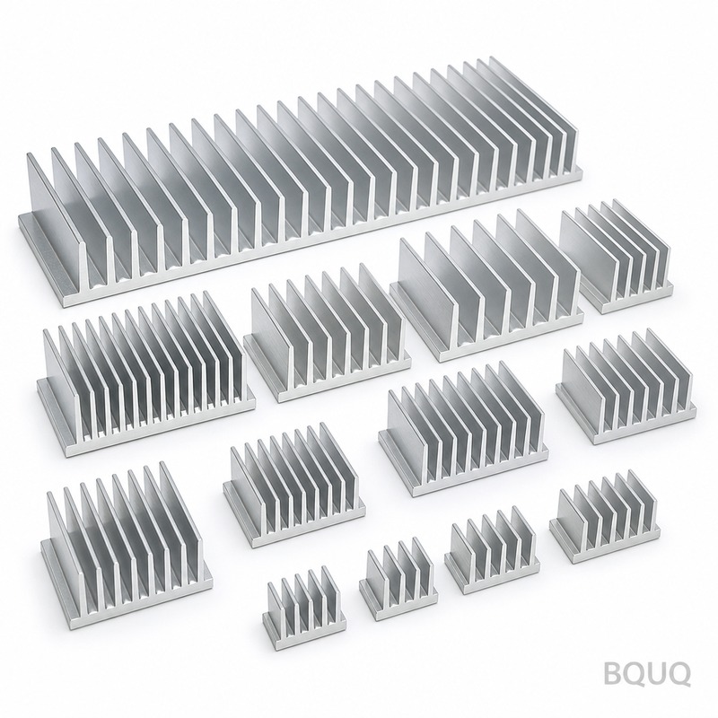
Environmental Factors and Derating
The LED current must be derated based on the heatsink's actual performance in the target environment. For indoor lighting at 25°C ambient, a 30W LED with a 1.2°C/W heatsink runs at Tj of 25 + 30 x (1.2 + 1.4) = 103°C, which is acceptable for a 105°C-rated LED but leaves no margin. For outdoor fixtures in 50°C ambient (direct sunlight on a black housing), the same design fails. BQUQ recommends derating the LED current by 15% for every 10°C above 25°C ambient. For a 50°C outdoor environment, a 30W LED should be driven at 25.5W, or the heatsink must be enlarged by 35%.
Humidity and salt spray also affect heatsink selection. In coastal or industrial environments, a bare aluminum heatsink will oxidize, increasing thermal resistance by 10-15% over 5 years. A hard anodize (25-50 microns) or a powder coat (50-80 microns) not only protects against corrosion but also increases emissivity from 0.1 (bare aluminum) to 0.85 (anodized), improving radiative heat transfer by up to 30% at high temperatures. For LED streetlights in coastal areas, BQUQ always specifies a chromate conversion coating plus a polyester powder coat, which passes a 500-hour salt spray test per ASTM B117.
Practical Recommendations for Production
For prototypes and low volumes (under 500 pieces), use extruded aluminum profiles with CNC machining. The tooling cost is low (under USD 1500), and you can test multiple fin geometries. For production volumes above 5000 pieces, evaluate stamped aluminum or die-cast if the power is under 20W, but do a thermal simulation first. BQUQ's experience shows that 70% of LED heatsink failures are not due to material but to poor TIM application or uneven clamping pressure. Specify a screw torque of 4-6 kgf-cm for M3 screws on the LED module, and use a torque-controlled driver.
Always request a thermal test report from your supplier showing the actual Rth hs at the operating current, not just the theoretical value. A proper test uses a thermocouple on the LED case, a constant current power supply, and an ambient-controlled chamber at 25°C and 50°C. Ask for the temperature rise curve over 60 minutes; a heatsink that reaches steady state in under 30 minutes is well-designed, while one that keeps heating suggests inadequate surface area.
FAQ-Style Tips for Engineers
Q: Can I use a smaller heatsink if I add a fan? Yes, forced convection reduces required surface area by 50-60%, but the fan adds 2-3W power draw and a failure point. For outdoor lighting, fan reliability is unacceptable; always use natural convection.
Q: What is the maximum safe heatsink base temperature? Keep the LED case temperature below 85°C for 50,000-hour lifespan. Every 10°C above 85°C cuts the LED lifetime by half, per the Arrhenius equation.
Q: How do I choose between anodize and powder coat? Anodize (10-20 microns) is best for thermal performance because it adds less than 0.05°C/W resistance. Powder coat is thicker (50-80 microns) and adds 0.1-0.2°C/W but provides superior UV and scratch resistance for outdoor fixtures.
Q: What is the minimum gap between fins for dust-prone environments? For factory or warehouse lights, maintain at least 10mm fin spacing so dust does not bridge the fins. If dust accumulates, it acts as insulation, increasing Rth by 20-30% per year without cleaning.
Conclusion and Contact
The correct LED heat sink is determined by a simple thermal budget calculation, but the practical selection requires balancing material, manufacturing process, and environmental derating. For powers under 15W, stamped aluminum is cost-effective; for 15W to 100W, extruded 6063-T5 is the standard; above 100W, bonded fin or skived copper is necessary. Always specify a machined flat mounting surface, use a high-quality TIM, and test the actual thermal resistance at your operating point. If you provide your LED power, ambient temperature, and target Tj, BQUQ can recommend a specific heatsink geometry and provide a thermal simulation within 24 hours.
At BQUQ, our 20 years of CNC machining and thermal management experience ensures your LED heatsink meets both thermal and cost targets. We offer free thermal resistance testing and DFM feedback on your CAD files. For a quotation within 12 hours, email your 2D/3D drawing and power requirements to sc@bquq.com or contact us on WhatsApp at +86 13713157787. Visit www.bquq.com to view our standard extrusion profiles and thermal test data.


