
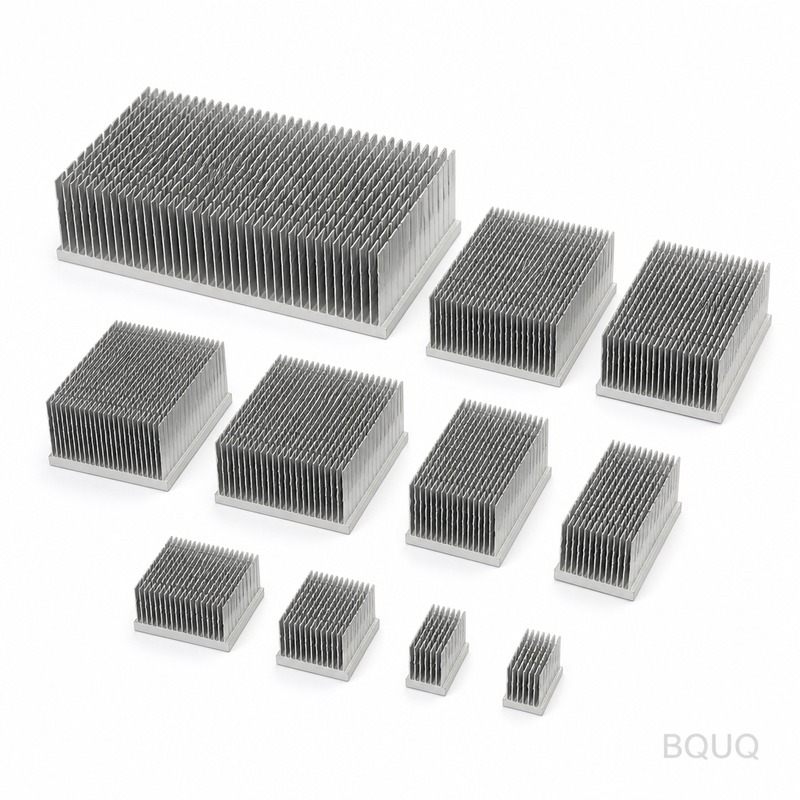
How to Choose a Heat Sink for MOSFETs and Power Semiconductors
Selecting a heat sink for MOSFETs and power semiconductors requires a thermal resistance calculation that balances junction temperature, ambient temperature, and power dissipation. The target is to keep the junction temperature (Tj) below 150°C for silicon devices, with a safety margin of 20-25°C, while optimizing for cost, space, and airflow. For a typical TO-247 package dissipating 50W, a heat sink with a thermal resistance of 1.2°C/W or lower is necessary at a 50°C ambient with forced airflow.
Thermal Resistance Path and Calculation
The thermal path from the silicon die to the ambient air consists of three primary resistances: junction-to-case (RθJC), case-to-sink (RθCS), and sink-to-ambient (RθSA). The total thermal resistance (RθJA) is the sum of these three values, and the junction temperature is calculated as Tj = Ta + (P × RθJA), where Ta is ambient temperature and P is power dissipation in watts.
For a practical example, consider an IRFP460 MOSFET in a TO-247 package dissipating 40W. The RθJC is 0.45°C/W, and with a mica insulator and thermal grease, RθCS is approximately 0.5°C/W. If the ambient temperature is 40°C and the maximum allowable Tj is 150°C, the required RθSA is (150 - 40) / 40 - 0.45 - 0.5 = 1.8°C/W. A standard extruded aluminum heat sink with dimensions 100mm x 60mm x 40mm, with natural convection, offers approximately 2.5°C/W, which is insufficient. The engineer must either increase the surface area, add forced airflow, or reduce the power dissipation.
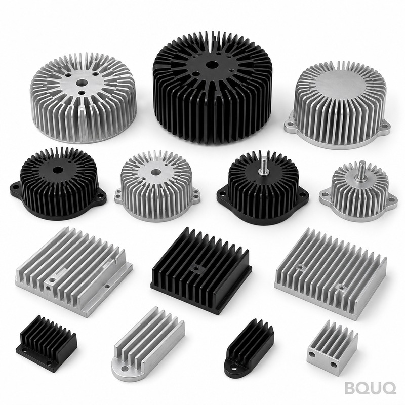
Material Selection: Aluminum vs. Copper
Aluminum 6063-T5 is the industry standard for heat sinks due to its cost-effectiveness, weight, and adequate thermal conductivity of 201 W/m·K. Copper offers 401 W/m·K, which is nearly double the thermal conductivity, but it is 3-4 times more expensive per kilogram and weighs 3.3 times more than aluminum. For most MOSFET applications, aluminum is the rational choice unless space constraints are extreme or the power density exceeds 100W per 100mm length of heat sink.
For high-frequency switching applications where the heat sink also serves as a ground plane, copper is sometimes specified, but nickel-plated aluminum is a more practical alternative. BQUQ uses 6063-T5 aluminum for 90% of its heat sink production, with 1050 aluminum used for stamping-based heat sinks due to its superior formability, despite a slightly lower thermal conductivity of 222 W/m·K.
| Material | Thermal Conductivity (W/m·K) | Cost per kg (USD) | Density (g/cm³) | Typical Use Case |
| Aluminum 6063-T5 | 201 | 3.50 | 2.70 | Extruded heat sinks, general purpose |
| Aluminum 1050 | 222 | 3.20 | 2.70 | Stamped fin heat sinks, LED lighting |
| Copper C11000 | 401 | 12.00 | 8.96 | High-density power modules, IGBTs |
| Aluminum 6061-T6 | 167 | 3.80 | 2.70 | Machined heat sinks with mounting holes |
Heat Sink Geometry and Fin Configuration
The geometry of the heat sink directly affects the convective heat transfer coefficient. For natural convection, the optimal fin spacing is typically between 6mm and 10mm, depending on the fin height, to allow for undisturbed airflow. Fin thickness should be between 1.5mm and 3.0mm for extruded profiles, and fin height should not exceed 10 times the fin spacing to avoid airflow stagnation.
For forced convection with a fan velocity of 3 m/s, fin spacing can be reduced to 3mm to 5mm, and fin height can be increased to 50mm or more. The pressure drop across the fins must be calculated to ensure the selected fan provides adequate static pressure. A 100mm x 100mm x 50mm heat sink with 4mm fin spacing and 2mm fin thickness has a surface area of approximately 0.8 m², which yields a thermal resistance of 0.8°C/W at 3 m/s airflow, versus 2.8°C/W in natural convection.
Bending or stamping fins, common in BQUQ's production, allows for a higher fin density (up to 10 fins per inch) and a lighter weight compared to extrusion. However, the thermal contact resistance between the stamped fin and the base plate must be considered, typically adding 0.1-0.3°C/W to the total resistance. Soldered or brazed joints are superior to mechanical crimping, reducing this added resistance to below 0.05°C/W.
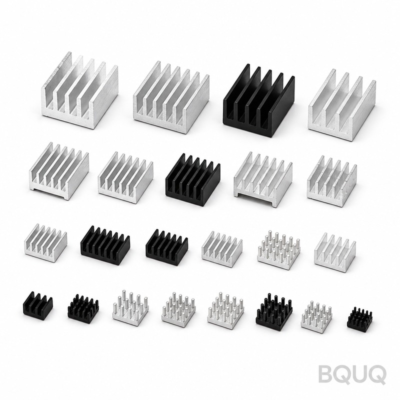
Mounting Methods and Thermal Interface Materials
The interface between the semiconductor package and the heat sink is often the most overlooked source of thermal failure. A bare TO-220 package mounted directly on aluminum has an RθCS of approximately 1.0°C/W due to surface roughness. Applying a 25-micron layer of thermal grease (silicone-based, with thermal conductivity of 0.8 W/m·K) reduces RθCS to 0.2°C/W. For higher performance, phase-change materials or graphite pads with a conductivity of 5 W/m·K can achieve RθCS values of 0.1°C/W.
The mounting pressure is equally critical. For TO-220 and TO-247 packages, the recommended screw torque is 0.5-0.7 N·m. Under-torqueing increases RθCS significantly, while over-torqueing can crack the plastic package or deform the heat sink surface. BQUQ recommends using a spring washer and a flat washer to maintain consistent pressure across temperature cycling, as aluminum expands at 23 ppm/°C, while the copper lead frame expands at 17 ppm/°C, creating differential stress at the interface.
For high-voltage applications exceeding 500V, electrical isolation is mandatory. The options are an anodized aluminum surface (breakdown voltage 500-1000V, but with an added thermal resistance of 0.3-0.5°C/W) or a 0.5mm thick alumina ceramic pad (breakdown voltage 2000V, RθCS of 0.4°C/W). Mica washers, while cheap at 0.02 USD per piece, have a high RθCS of 0.8°C/W and are fragile; they should be avoided in production environments.
Cost Breakdown and Lead Time Considerations
The cost of a heat sink scales with the manufacturing process. Extruded aluminum heat sinks have a low tooling cost of 300-800 USD for a standard die, making them economical for quantities above 500 pieces. The unit price for a 100mm x 60mm x 40mm extrusion is 2.50-4.00 USD in quantities of 1000, with a lead time of 2-3 weeks including anodizing.
Stamped heat sinks, made from 0.5mm to 1.0mm aluminum sheet, have a higher tooling cost of 2000-5000 USD for a progressive die, but the unit price drops to 1.20-2.00 USD for quantities above 5000 pieces. Lead time is 4-5 weeks due to die fabrication. For prototyping or low-volume production under 100 pieces, a CNC-machined heat sink from a solid block is the fastest option, with a lead time of 3-5 days but a unit price of 15-25 USD.
| Manufacturing Process | Tooling Cost (USD) | Unit Price (1000 pcs) | Lead Time | Min Quantity |
| Extrusion (100x60x40mm) | 500 | 3.20 | 2-3 weeks | 500 |
| Stamping (0.8mm sheet) | 3500 | 1.80 | 4-5 weeks | 3000 |
| CNC Machining (from billet) | 0 | 18.00 | 3-5 days | 1 |
| Die Casting (A380 aluminum) | 8000 | 2.50 | 6-8 weeks | 2000 |
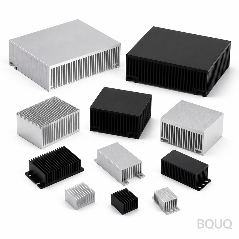
Forced Airflow and System-Level Integration
Natural convection is often insufficient for MOSFETs dissipating more than 20W. Adding a 40mm x 40mm x 10mm axial fan with a flow rate of 10 CFM and 0.2-inch static pressure reduces the thermal resistance of a typical heat sink by 50-70%. The system designer must consider the fan's reliability, as a fan failure will lead to rapid thermal runaway. A thermal derating strategy in the firmware, reducing the switching frequency or current limit when the heat sink temperature exceeds 85°C, is a standard protective measure.
For liquid cooling, which is increasingly used in electric vehicle inverters, the heat sink is replaced by a cold plate with internal channels. The thermal resistance of a liquid-cooled cold plate is 0.05-0.1°C/W, an order of magnitude better than air cooling. The cost, however, jumps to 50-100 USD per unit, and the system requires a pump, radiator, and coolant, adding complexity and potential leak points.
The placement of the heat sink relative to other components on the PCB also matters. A heat sink should not be placed directly above or below a power inductor, as the magnetic field will induce eddy currents in the aluminum, causing localized heating. A separation of at least 10mm is recommended. Furthermore, the heat sink should be oriented with the fins vertical for natural convection to promote the chimney effect, which improves airflow by 15-20% compared to horizontal fin orientation.
FAQ-Style Recommendations for Engineers
What is the maximum safe Tj for a silicon MOSFET? The datasheet absolute maximum is usually 150°C or 175°C, but for long-term reliability of greater than 10 years, keep Tj below 120°C. Every 10°C reduction in Tj doubles the mean time between failures.
Should I use a heat sink with a black anodized coating? Yes. Black anodizing increases the emissivity from 0.05 for bare aluminum to 0.85, improving the radiative heat transfer by up to 30% in natural convection. The anodizing layer is 10-25 microns thick and adds 0.1-0.2°C/W of thermal resistance, which is negligible compared to the radiative benefit.
How do I calculate the required heat sink size for an unknown power dissipation? Use an oscilloscope with a current probe to measure the actual RMS current through the MOSFET and the VDS voltage drop during conduction. Multiply these to get conduction loss. Add the switching loss, which is approximately 0.5 × VDS × ID × (t_rise + t_fall) × f_switch. Sum these to get total power dissipation, then use the thermal resistance formula.
What is the tolerance on thermal resistance values? The RθSA values quoted by heat sink manufacturers are measured under ideal laboratory conditions with a uniform heat source. In real applications, the thermal resistance can be 20-30% higher due to non-uniform heating and boundary layer effects. Always derate the calculated RθSA by a factor of 1.25.
Conclusion and Engineering Recommendation
The selection of a heat sink for MOSFETs and power semiconductors is a deterministic engineering process, not a guess. Calculate the power dissipation, determine the allowable thermal resistance, then select the material, geometry, and manufacturing process that meets the thermal budget at the lowest total cost. For production volumes above 1000 units, extruded aluminum with a black anodized finish is the most cost-effective solution. For high-density or automotive applications, consider stamped fins with soldered joints or liquid-cooled cold plates.
At BQUQ, our 20 years of experience in CNC machining, metal stamping, and heat sink fabrication allows us to deliver components with a tolerance of ±0.05mm on mounting surfaces and a surface flatness of 0.02mm. Our standard lead time is 2 weeks for extruded profiles and 5 days for CNC prototypes. We provide free thermal simulation reports with every quotation, ensuring that the heat sink you receive meets your Tj requirements, not just the datasheet claims.
For an accurate quote within 12 hours, send your 3D model, power dissipation, and ambient temperature to our engineering team. Email: sc@bquq.com, WhatsApp: +86 13713157787, www.bquq.com. We will provide a thermal simulation and a cost breakdown for the optimal heat sink solution for your specific application.


