
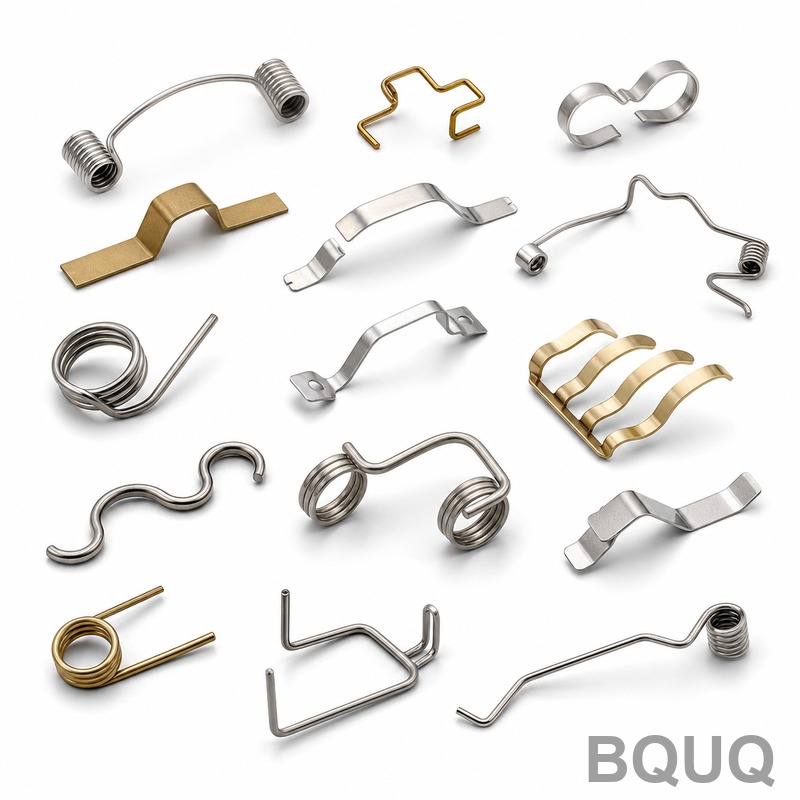
How to Choose Spring Wire Diameter for Load and Space Limits?
The correct spring wire diameter is the largest diameter that fits within your space envelope while delivering the required force at your defined deflection, because spring rate scales with the fourth power of wire diameter. For a given load, increasing wire diameter by 10% increases stiffness by approximately 46%, which means you must balance load capacity against available coil count and solid height. This article provides the calculation method, material limits, and practical selection rules used by BQUQ engineers for CNC-machined and stamped springs.
What Is the Direct Relationship Between Wire Diameter and Spring Load?
Spring rate (k) for a compression spring is calculated as k = (G × d⁴) / (8 × D³ × N), where G is the shear modulus of the material, d is wire diameter, D is mean coil diameter, and N is the number of active coils. Because d is raised to the fourth power, a small change in wire diameter has a disproportionate effect on load capacity. For example, increasing wire diameter from 1.0 mm to 1.1 mm (10% increase) raises the spring rate by 46.4%, assuming all other dimensions remain constant. This means that if your load requirement increases by 20%, you do not need a 20% larger wire; a 5% increase in wire diameter will typically suffice, but you must verify the stress level.
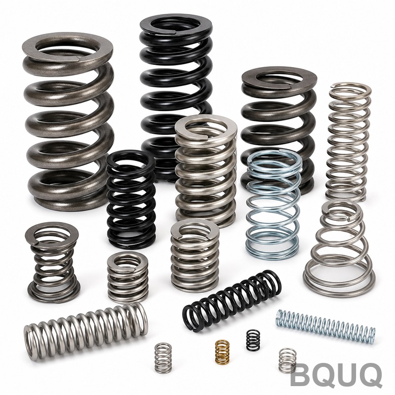
How Do You Calculate the Minimum Wire Diameter for a Given Load?
The minimum wire diameter is derived from the maximum allowable shear stress (τ) using the formula τ = (8 × F × D) / (π × d³) × K, where F is the maximum load, D is the mean coil diameter, and K is the Wahl correction factor (typically 1.1 to 1.3 for springs with D/d ratios below 8). Rearranged, the minimum diameter is d = (8 × F × D × K / (π × τ_allow))^(1/3). For a spring requiring 500 N load, mean coil diameter of 20 mm, Wahl factor of 1.2, and allowable shear stress of 800 MPa for music wire, the minimum wire diameter is (8 × 500 × 20 × 1.2 / (π × 800))^(1/3) = 3.07 mm. Always add a 10% safety margin, so specify 3.4 mm or larger.
What Space Constraints Limit the Maximum Wire Diameter?
The primary space constraints are the outer diameter (OD) of the spring, the solid height (when coils are fully compressed), and the required number of active coils. The solid height is approximately N × d, so a larger wire diameter increases the compressed length, which may exceed your available space. Additionally, the ratio of mean coil diameter to wire diameter (D/d) must stay between 4 and 16; below 4, the spring is difficult to wind and stress concentration is severe, while above 16, the spring may buckle. For a given OD of 25 mm and a required solid height under 20 mm, the maximum wire diameter is 20 / N, and if you need 6 active coils, the wire cannot exceed 3.3 mm.
Which Material Properties Affect Wire Diameter Selection?
The shear modulus (G) and maximum allowable shear stress (τ_allow) are the two material properties that directly influence wire diameter. Music wire (ASTM A228) has a G of 79.3 GPa and an allowable stress of 45% of tensile strength (up to 830 MPa for 3 mm wire). Stainless steel 302 (ASTM A313) has a lower G of 69 GPa and allowable stress of 40% of tensile strength (around 600 MPa), requiring a larger diameter for the same load. Chrome vanadium (ASTM A231) offers 80 GPa and 50% allowable stress (up to 1000 MPa), allowing the smallest wire diameter for high-stress applications. The following table shows the impact of material on minimum wire diameter for a 500 N load, 20 mm mean coil diameter, and 6 active coils:
| Material | Shear Modulus (GPa) | Allowable Stress (MPa) | Minimum Wire Diameter (mm) | Recommended Wire Diameter (mm) |
| Music Wire A228 | 79.3 | 830 | 3.07 | 3.40 |
| Stainless 302 A313 | 69.0 | 600 | 3.47 | 3.80 |
| Chrome Vanadium A231 | 80.0 | 1000 | 2.88 | 3.20 |
| Oil-Tempered A229 | 79.3 | 700 | 3.26 | 3.60 |
How Do You Verify That the Selected Wire Diameter Fits the Space Envelope?
After calculating the wire diameter, you must check three geometric constraints: outer diameter (OD), solid height, and free length. If the OD is fixed, the mean coil diameter D = OD – d, and you need to recalculate the spring rate with this new D. If the solid height (N × d) exceeds the available compressed length, you must reduce the number of active coils or accept a lower load. For a spring with OD 25 mm, wire diameter 3.4 mm, and 6 active coils, the solid height is 20.4 mm, leaving no gap for full compression. You would need to reduce N to 5, which increases the spring rate by 20%, or reduce the wire diameter to 3.2 mm to achieve a solid height of 19.2 mm.
Why Is the D/d Ratio Critical for Spring Manufacturing?
The D/d ratio (mean coil diameter divided by wire diameter) determines manufacturability and fatigue life. For CNC-machined springs and precision stamping, a D/d ratio below 4 causes excessive stress on the inner surface of the coil, leading to premature cracking under cyclic loading. A ratio above 16 creates a slender spring that buckles laterally under compression, especially if the free length is more than 4 times the mean coil diameter. The optimal range is 6 to 10, where the Wahl correction factor is moderate (1.1 to 1.2) and the spring can be wound without special tooling. For a wire diameter of 3.4 mm and a mean coil diameter of 21.6 mm (OD 25 mm), the D/d ratio is 6.35, which is near the lower end of the optimal range but acceptable.
Can You Use a Thinner Wire with More Coils to Meet Load Requirements?
Yes, but with trade-offs in space and fatigue life. Since spring rate is proportional to 1/N, reducing wire diameter from 3.4 mm to 3.0 mm (a 12% reduction) decreases stiffness by 41%, so you would need to increase the number of active coils by 70% to maintain the same load. For a spring with a fixed OD of 25 mm, this increases the solid height from 20.4 mm to 30.6 mm (6 coils at 3.0 mm plus additional coils), which may exceed the available compressed space. Thinner wires also have lower allowable stress due to surface defects, reducing fatigue life by up to 50% for every 0.5 mm reduction in diameter. Therefore, only use thinner wire when the space envelope is tall and the load is static, not cyclic.
What Tolerance Should You Specify for Wire Diameter?
Wire diameter tolerance depends on the material grade and the manufacturing process. For music wire and oil-tempered wire, the standard tolerance is ±0.03 mm for diameters up to 3.0 mm, and ±0.05 mm for diameters from 3.0 mm to 6.0 mm. Stainless steel wire has a slightly wider tolerance of ±0.05 mm for small diameters. Since spring rate is proportional to d⁴, a tolerance of ±0.03 mm on a 3.0 mm wire results in a ±4% variation in spring rate, which is acceptable for most applications. For precision springs with a required load tolerance of ±2%, you must select wire with a tighter tolerance of ±0.01 mm, available as specialty ground wire at a 15-20% cost premium.
What Are the Practical Steps to Finalize Wire Diameter Selection?
First, define the maximum load and required deflection, and measure the available space envelope (OD, ID, and compressed length). Second, calculate the minimum wire diameter using the allowable stress formula and add a 10% safety margin. Third, check the solid height and D/d ratio; if either fails, adjust the number of coils or switch to a higher-strength material like chrome vanadium. Fourth, verify the spring rate using the exact wire diameter and mean coil diameter, and confirm it is within ±5% of the target. Finally, specify the wire diameter tolerance and surface finish (shot peening for fatigue) in your engineering drawing. For prototypes, BQUQ recommends ordering three wire diameters (calculated value, plus 0.1 mm and minus 0.1 mm) to empirically verify load behavior before mass production.
How Does Temperature Affect Wire Diameter Selection?
Temperature affects the shear modulus and allowable stress of spring materials. Music wire loses 10% of its shear modulus at 100°C and 20% at 150°C, meaning a spring will deliver less load at elevated temperatures. Stainless steel 302 maintains its modulus up to 300°C but has a lower allowable stress. For applications above 150°C, use chrome vanadium or Inconel X-750, which retains 90% of its room-temperature properties up to 400°C. When operating at high temperatures, increase the wire diameter by 5-10% to compensate for the reduced modulus, and always specify the maximum operating temperature on the drawing.
FAQ
What is the first step in choosing spring wire diameter?
Define the maximum load, required deflection, and available space envelope (outer diameter, inner diameter, and solid height). These three parameters dictate the minimum wire diameter, the number of coils, and the material selection.
Can I use a standard wire diameter instead of a calculated value?
Yes, standard wire diameters (e.g., 1.0 mm, 1.2 mm, 1.5 mm, 2.0 mm, 3.0 mm, 3.5 mm) are available at lower cost and shorter lead times. Select the next larger standard diameter above your calculated minimum, then recalculate the spring rate and adjust the number of coils.
How much does wire diameter affect the cost of a spring?
Larger wire diameters cost more per kilogram (about 10-15% more for each 0.5 mm increase) but require fewer coils, so the total material cost may be similar. The dominant cost factor is the number of manufacturing steps, not the wire diameter itself.
What is the maximum wire diameter for CNC machining of springs?
For CNC coil winding, the maximum wire diameter is typically 12 mm for cold-formed springs and up to 25 mm for hot-wound springs. Above 12 mm, you need specialized equipment and heat treatment, which increases lead time to 3-4 weeks.
How do I know if my spring will buckle with the selected wire diameter?
Check the slenderness ratio (free length divided by mean coil diameter). If it exceeds 4, the spring will buckle under compression. Use a larger wire diameter to shorten the free length, or add a guide rod, or reduce the number of coils.
What is the minimum wire diameter for a stamped spring?
For metal stamping, the minimum wire diameter is limited by the stamping die, typically 0.2 mm for thin sheet and 1.0 mm for wire-formed parts. Below 0.2 mm, the material is difficult to handle and tolerances become impractical.
Should I choose a larger wire diameter for higher fatigue life?
Yes, a larger wire diameter reduces the stress level for the same load, which increases fatigue life. For infinite life (over 10 million cycles), keep the maximum shear stress below 35% of the tensile strength, which may require a wire diameter 10-20% larger than the static load calculation.
Conclusion
Selecting the correct spring wire diameter requires balancing the fourth-power stiffness relationship against solid height, D/d ratio, and material allowable stress. Always calculate the minimum diameter from the load formula, add a 10% safety margin, and verify the space envelope before finalizing the drawing. For complex load and space constraints, BQUQ provides engineering support within 12 hours of your inquiry.
For a free design review and quotation within 12 hours, contact BQUQ at Email: sc@bquq.com, WhatsApp: +86 13713157787, or visit www.bquq.com. We have 20 years of experience in CNC machining, metal stamping, springs, and heat sinks, and we will recommend the optimal wire diameter for your specific load and space constraints.


