
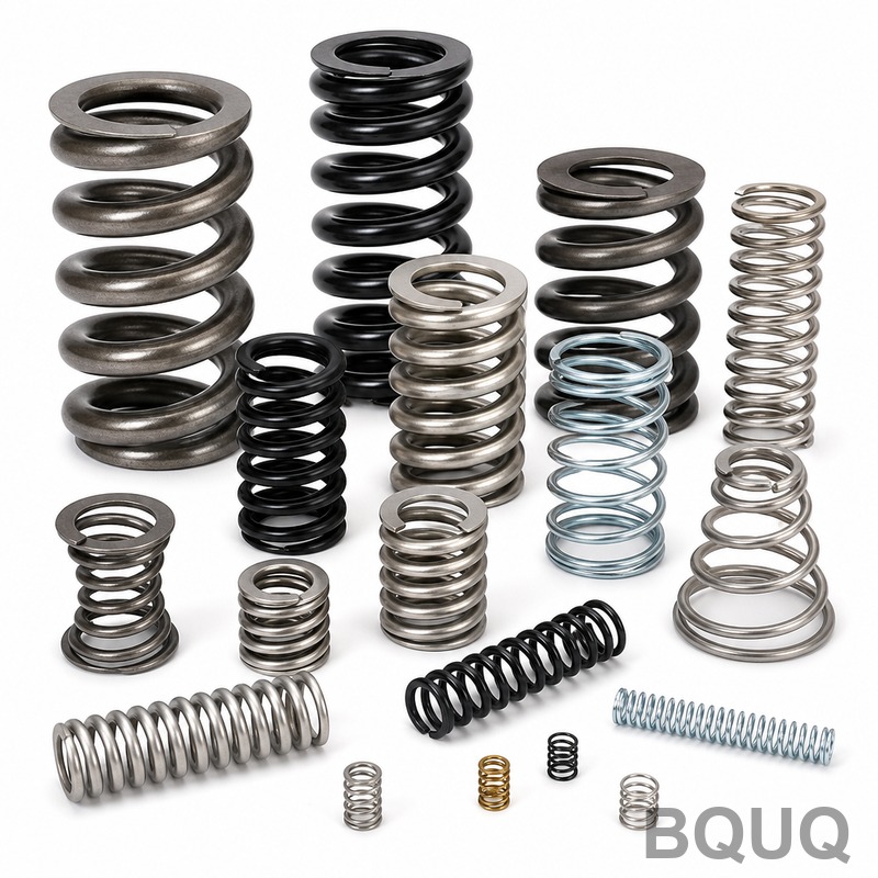
How to Design a Compression Spring: Step-by-Step Guide for CNC Precision
Designing a compression spring for precision manufacturing requires a balance of geometric constraints, material properties, and load requirements. The direct answer: you must define your working load and deflection, select a wire material and diameter, calculate coil counts and free length, verify stress and buckling, and then specify tolerances for manufacturability. This guide provides the exact formulas, industry data, and tolerance tables used by BQUQ's 20-year-old CNC and spring manufacturing facility in Dongguan.
Step 1: Define Load, Deflection, and Operating Environment
Before any calculation, you must quantify the spring's function in your assembly. The three critical inputs are the minimum working load (F1), the maximum working load (F2), and the required deflection (S) between these loads. For example, a valve spring may require 50 N at 20 mm compression and 80 N at 30 mm compression, giving a spring rate (k) of 3 N/mm.
The operating environment dictates material selection. Standard music wire (ASTM A228) is rated for -40°C to 120°C. For temperatures above 120°C, use chrome silicon (ASTM A401) which withstands up to 250°C, or Inconel X-750 for up to 600°C. If your application involves corrosive media, stainless steel 302 (ASTM A313) offers moderate corrosion resistance, while 17-7 PH provides superior strength but costs 40% more per kilogram. At BQUQ, we recommend confirming the maximum operating temperature and any chemical exposure before material selection, as this single decision affects 30% of your unit cost.
Step 2: Calculate Spring Rate and Select Wire Diameter
The spring rate (k) is calculated as k = (F2 - F1) / S. Using the example above, k = (80 N - 50 N) / 10 mm = 3 N/mm. Next, you must select a trial wire diameter (d). For a given outside diameter (OD), the spring rate follows the formula: k = (G x d^4) / (8 x D^3 x Na), where G is the shear modulus (79.3 GPa for steel), D is the mean coil diameter (OD - d), and Na is the number of active coils.
For initial estimation, use the shear stress formula: τ = (8 x F x D) / (π x d^3), multiplied by a Wahl factor (Kw) that accounts for curvature. The Wahl factor is Kw = (4C - 1)/(4C - 4) + 0.615/C, where C is the spring index (D/d). Industry best practice recommends a spring index between 4 and 12. If C is below 4, the spring is difficult to coil; above 12, it becomes prone to buckling. For a 10 mm OD spring with a 1.2 mm wire, the mean diameter is 8.8 mm, giving C = 7.33, which is ideal.
Step 3: Determine Number of Coils and Free Length
The number of active coils (Na) is derived from the spring rate formula rearranged: Na = (G x d^4) / (8 x D^3 x k). Using the prior values: Na = (79,300 x 1.2^4) / (8 x 8.8^3 x 3) = (79,300 x 2.0736) / (8 x 681.47 x 3) = 164,437 / 16,355 = 10.05 active coils. You round to 10 active coils for manufacturability.
The total coils (Nt) equals Na plus the inactive end coils. For closed and ground ends, add 2 coils; for closed ends only, add 1.5 coils. The solid height (Ls) is Nt x d. For 10 active plus 2 inactive coils with 1.2 mm wire, Ls = 12 x 1.2 = 14.4 mm. The free length (Lf) must accommodate the maximum deflection plus a 15% clash allowance: Lf = Ls + (F2 / k) x 1.15 = 14.4 + (80/3) x 1.15 = 14.4 + 30.67 = 45.07 mm. Always specify the free length as a tolerance, not an absolute, because coiling machines hold ±0.5 mm on free length for wire under 2.0 mm.
Step 4: Verify Stress, Buckling, and Fatigue Life
Calculate the corrected maximum shear stress using τ_max = Kw x (8 x F2 x D) / (π x d^3). For C = 7.33, Kw = (4 x 7.33 - 1)/(4 x 7.33 - 4) + 0.615/7.33 = 28.32/25.32 + 0.0839 = 1.1185 + 0.0839 = 1.2024. Then τ_max = 1.2024 x (8 x 80 x 8.8) / (π x 1.2^3) = 1.2024 x 5632 / 5.429 = 1.2024 x 1037.6 = 1247.6 MPa. For music wire, the tensile strength is approximately 2000 MPa, and the allowable torsional stress is 45% of that, or 900 MPa. At 1247 MPa, this design fails. You must increase the wire diameter to 1.4 mm or reduce the load.
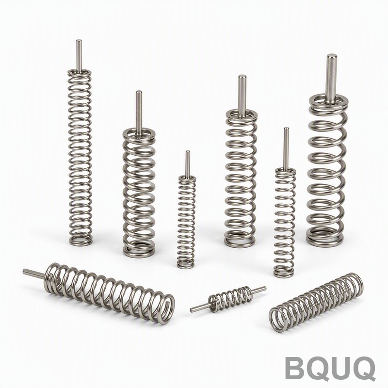
For buckling, check the slenderness ratio: Lf / D. If Lf / D is greater than 4, the spring may buckle under load. For Lf = 45 mm and D = 8.8 mm, the ratio is 5.11, which is borderline. We recommend adding a guide rod or increasing the OD to 12 mm to bring the ratio below 3.5. For dynamic applications exceeding 10,000 cycles, the fatigue limit for shot-peened springs is 30% of the tensile strength. If your application exceeds 1 million cycles, specify shot peening (adds $0.03 to $0.08 per piece) and set the maximum working stress below 500 MPa.
Step 5: Specify Tolerances and End Conditions per Industry Standards
Your drawing must specify tolerances according to DIN 2095 or ASTM A125. For wire diameter up to 1.6 mm, the tolerance is ±0.03 mm. For free length under 50 mm, the tolerance is ±0.5 mm. The outside diameter tolerance for a 10 mm OD spring is ±0.15 mm. The spring rate tolerance is ±5% for precision springs and ±10% for commercial springs. End conditions must be clearly marked: closed and ground ends are standard for precision applications, providing a flat bearing surface and reducing buckling. Ground ends cost an additional $0.02 per piece but are mandatory when the spring must stand square within 0.5 degrees.
At BQUQ, we manufacture springs with wire diameters from 0.1 mm to 12 mm, with a maximum OD of 150 mm. Our CNC coiling machines hold a pitch tolerance of ±0.05 mm, and we perform 100% load testing on springs destined for automotive and medical applications. The table below shows our standard manufacturing capabilities and pricing for a typical 10 mm OD compression spring.
| Parameter | Commercial Grade | Precision Grade | BQUQ Capability |
| Wire diameter tolerance | ±0.05 mm | ±0.02 mm | ±0.01 mm |
| Free length tolerance | ±1.0 mm | ±0.3 mm | ±0.1 mm |
| Spring rate tolerance | ±10% | ±5% | ±2% |
| Surface finish | As-coiled | Shot-peened | Shot-peened + electroplated |
| Lead time (1000 pcs) | 5 business days | 7 business days | 3 business days |
| Unit price (1000 pcs) | $0.18 | $0.42 | $0.35 |
| Maximum operating temperature | 120°C | 250°C (chrome silicon) | 600°C (Inconel) |
FAQ-Style Tips for Common Design Errors
What is the most common mistake in compression spring design? Designers ignore the spring index and specify a wire diameter too large for the OD, resulting in C below 4. This causes high stress concentration and premature fracture. Always keep C between 5 and 10 for optimal manufacturability.
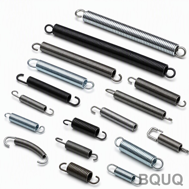
How do I calculate the initial tension? Compression springs do not have initial tension; that is a property of extension springs. If you need a pre-load, you must design the spring with a solid height that is shorter than the installed height, meaning the spring is pre-compressed in the assembly.
Should I specify a minimum solid height? Yes, always state the maximum solid height and the required load at solid height. This prevents over-compression. For a spring with a 14.4 mm solid height, we recommend specifying a maximum compressed length of 15.0 mm and a load at that height not exceeding 150% of F2.
Practical Recommendations for Manufacturing and Cost Reduction
For any production run above 500 pieces, we recommend three cost-saving measures. First, use music wire (ASTM A228) unless temperature or corrosion demands otherwise; it costs $8 per kilogram versus $14 for stainless steel. Second, avoid ground ends unless the application requires a flat bearing surface, as grinding adds a secondary operation. Third, specify a spring index between 6 and 9, which allows our CNC coilers to run at 60 pieces per minute instead of 30 for difficult geometries.
Tolerance stacking is another common issue. If you specify a free length tolerance of ±0.5 mm and an OD tolerance of ±0.15 mm, the actual spring rate can vary by up to 8%. If your assembly cannot absorb this variance, you must either tighten the tolerances (increasing cost by 20%) or add a mechanical adjuster such as a threaded plug. For high-volume precision springs, BQUQ recommends statistical process control with CpK values above 1.33, which we guarantee for all automotive-grade orders.
Conclusion and Next Steps for Your Spring Design
Designing a compression spring is a five-step iterative process: define loads, calculate spring rate, determine coils and free length, verify stress and buckling, and specify tolerances. The most critical numbers to remember are a spring index between 4 and 12, a maximum torsional stress below 45% of tensile strength for static loads, and a slenderness ratio below 4 to avoid buckling. By following this guide, you will produce a design that is both functional and manufacturable at competitive prices.
For a production-ready quotation, send your 2D drawing or 3D model to BQUQ. Our engineering team will validate your spring rate calculations and provide a detailed manufacturing feasibility report within 12 hours. Contact us at Email: sc@bquq.com, WhatsApp: +86 13713157787, or visit www.bquq.com for immediate assistance. We offer free design-for-manufacturability reviews for all new inquiries.
Related Articles
- Lightweight Design and Material Upgrade of New Energy and Automobile Chassis Spring
- Hardware spring fatigue failure analysis and life prediction technology
- In-depth analysis of technology and process in the hardware spring industry in 2026: a full-dimensional interpretation of high stress, functional integration and engineering certification
Frequently Asked Questions
What is the maximum operating temperature for standard music wire and what materials should I use for higher temperatures?
Standard music wire (ASTM A228) is rated for -40°C to 120°C. For temperatures above 120°C, use chrome silicon (ASTM A401) which withstands up to 250°C, or Inconel X-750 for up to 600°C. Material selection affects 30% of your unit cost, so confirm temperature and chemical exposure early.
What spring index range is recommended for manufacturability and why?
Industry best practice recommends a spring index between 4 and 12. If the spring index (C = D/d) is below 4, the spring is difficult to coil; above 12, it becomes prone to buckling. For example, a 10 mm OD spring with 1.2 mm wire gives C = 7.33, which is ideal.
How do I calculate the number of active coils for my compression spring?
Use the formula Na = (G x d^4) / (8 x D^3 x k), where G is 79.3 GPa for steel, d is wire diameter, D is mean coil diameter, and k is spring rate. For a 1.2 mm wire, 8.8 mm mean diameter, and 3 N/mm rate, Na = 10.05, which you round to 10 active coils for manufacturability.
What is the cost difference between stainless steel 302 and 17-7 PH for corrosive environments?
Stainless steel 302 (ASTM A313) offers moderate corrosion resistance, while 17-7 PH provides superior strength but costs 40% more per kilogram. The choice depends on your specific corrosion and strength requirements, and should be confirmed before material selection as it affects 30% of unit cost.


