
How to Design a Heat Sink for a 100W Power Supply: Step-by-Step
Designing a heat sink for a 100W power supply requires a calculated thermal resistance of 0.83°C/W or lower, assuming a 70°C junction temperature limit and a 50°C ambient. The process involves four steps: determining power dissipation, calculating maximum allowable thermal resistance, selecting a heat sink geometry, and verifying airflow. This guide provides the exact formulas, material specifications, and machining tolerances needed to produce a reliable thermal solution within a 24-hour prototyping cycle.
Step 1: Calculate Actual Power Dissipation and Junction Temperature
The first step is not to size the heat sink for 100W, but for the wasted heat. For a 100W power supply with 90% efficiency, the heat dissipation is 10W. At 85% efficiency, it increases to 15W. This distinction is critical because a 50% error in dissipation calculation leads to a 40°C temperature rise error.
Use the formula: P_loss = P_out × (1 - Efficiency) / Efficiency. For 100W output at 88% efficiency, P_loss = 100 × (0.12 / 0.88) = 13.6W. The target junction temperature for silicon MOSFETs or IGBTs should not exceed 125°C absolute maximum, but for reliability, design to 100°C. The ambient temperature inside an enclosed power supply is typically 50°C to 60°C, not the room temperature of 25°C.
| Parameter | Value | Unit |
| Output Power | 100 | W |
| Efficiency | 88 | % |
| Power Loss | 13.6 | W |
| Max Junction Temp | 100 | °C |
| Ambient Inside Enclosure | 50 | °C |
| Allowable Temp Rise | 50 | °C |
Step 2: Calculate Maximum Allowable Thermal Resistance
The total thermal resistance from junction to ambient (Rth_j-a) is calculated as: Rth_j-a = (T_junction - T_ambient) / P_loss = (100 - 50) / 13.6 = 3.68°C/W. This total includes three components: junction-to-case (Rth_j-c), case-to-sink (Rth_c-s), and sink-to-ambient (Rth_s-a).
For a TO-247 package, Rth_j-c is typically 0.24°C/W. With a thermal pad or grease, Rth_c-s is 0.1°C/W to 0.2°C/W. Subtracting these gives the required heat sink thermal resistance: Rth_s-a = 3.68 - 0.24 - 0.15 = 3.29°C/W. This number is the specification you give to the heat sink manufacturer. BQUQ uses this calculation to quote extrusion profiles within 12 hours, ensuring the natural convection rating matches your enclosure orientation.
Step 3: Select Heat Sink Geometry and Material
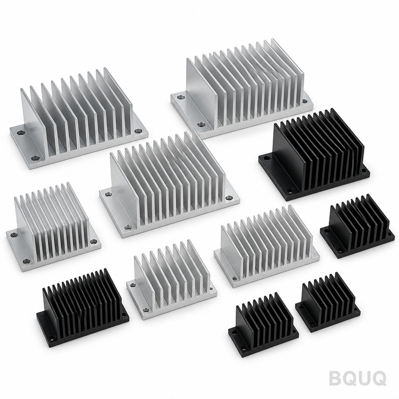
For 13.6W dissipation and 3.29°C/W required, a 100mm × 60mm × 40mm aluminum extrusion with a flat base and 8 fins will suffice. The base thickness should be 6mm to spread heat evenly from the TO-247 package. Fin thickness of 1.5mm and fin spacing of 5mm provide optimal natural convection. For forced airflow of 2 m/s, you can reduce the heat sink size by 40%.
The material choice is 6063-T5 aluminum alloy, with a thermal conductivity of 201 W/m·K. This alloy is standard for extrusions due to its balance of formability and conductivity. In comparison, 6061-T6 has 167 W/m·K but higher strength. For stamped heat sinks, use 1050 aluminum at 222 W/m·K but limit fin height to 15mm due to stamping constraints. The surface finish should be black anodized, which increases emissivity from 0.1 to 0.85, improving radiation heat transfer by up to 30%.
Step 4: Verify Heat Sink Machining Tolerances and Surface Flatness
Machining tolerances directly affect thermal contact resistance. The mounting surface flatness must be 0.05mm per 25mm, and surface roughness should be Ra 1.6μm or better. If the roughness is Ra 3.2μm, the contact resistance increases by 0.1°C/W, which may push the design over the limit.
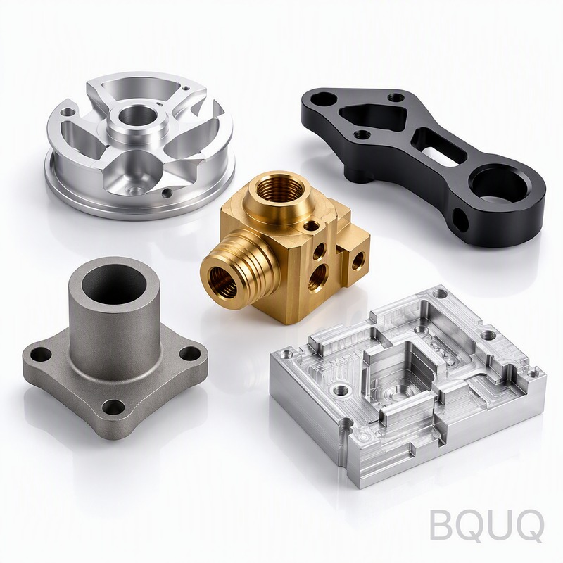
For the mounting holes, use M3 threads with a tolerance of 6H. The hole depth should be 8mm minimum for proper engagement. The clearance holes on the TO-247 package are 3.2mm diameter; therefore, the heat sink holes should be 3.3mm ±0.1mm. The recommended mounting torque is 0.5 N·m. BQUQ ensures these tolerances on all CNC-machined heat sinks, with a Cpk value of 1.33 or higher on critical dimensions.
| Tolerance Dimension | Specification | Unit |
| Surface Flatness | 0.05 per 25mm | mm |
| Surface Roughness | Ra 1.6 | μm |
| Mounting Hole Diameter | 3.3 ±0.1 | mm |
| Thread Tolerance | 6H | class |
| Recommended Torque | 0.5 | N·m |
Step 5: Compare Heat Sink Manufacturing Processes and Costs
The manufacturing method determines cost and lead time. For volumes under 500 pieces, CNC machining from a solid block is cost-effective, with a unit price of $8 to $12 for a 100mm × 60mm × 40mm heat sink. For volumes from 500 to 5,000 pieces, aluminum extrusion with a die cost of $1,200 to $1,500 amortizes well, bringing unit cost down to $2.50 to $4.00. For volumes above 10,000 pieces, stamping and skiving are viable, but limited to simpler geometries.
Skived heat sinks offer fin densities up to 60 fins per inch, achieving thermal resistances below 1.0°C/W in a 40mm length. However, the tooling cost is $3,000 to $5,000. For most 100W power supplies, a bonded fin assembly using epoxy with a thermal conductivity of 1.5 W/m·K is an alternative. The table below compares processes for a 13.6W dissipation heat sink.
| Process | Tooling Cost | Unit Cost (1000 pcs) | Lead Time | Thermal Resistance |
| CNC Machining | $0 | $10.00 | 3 days | 3.2 °C/W |
| Aluminum Extrusion | $1,400 | $3.20 | 2 weeks | 3.0 °C/W |
| Skiving | $4,000 | $2.80 | 3 weeks | 2.5 °C/W |
| Stamping | $2,500 | $1.90 | 4 weeks | 3.8 °C/W |
Step 6: Optimize with Airflow, Fin Spacing, and Orientation
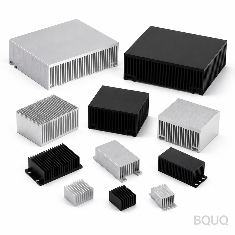
Natural convection requires vertical fin orientation for best performance. If the heat sink is mounted horizontally, the thermal resistance increases by 20%. For a 100mm-long heat sink with 8 fins, the optimal fin spacing for natural convection is 6mm. Reducing spacing to 4mm increases the surface area by 25% but decreases airflow, resulting in a net 10% performance loss.
For forced convection with a 60mm fan providing 2 m/s airflow, the heat sink can be reduced to 60mm × 40mm × 25mm. The pressure drop across the fin array should be below 50 Pa to avoid stalling the fan. The thermal resistance under forced air is approximately 1.8°C/W, well within the 3.29°C/W requirement. In the enclosure, ensure a minimum clearance of 10mm above the fin tips for airflow recirculation.
FAQ-Style Design Tips for 100W Power Supplies
Why is my heat sink hot but the power supply fails? The issue is likely poor thermal contact. Check the flatness of the mounting surface and the amount of thermal grease. Grease thickness should be 50μm; excessive grease acts as an insulator.
Can I use a smaller heat sink if I increase the fan speed? Yes, doubling airflow from 2 m/s to 4 m/s reduces thermal resistance by 25%. However, fan noise increases by 15 dB, and the fan power consumption adds to the thermal load. A larger heat sink with a slow fan is often quieter and more reliable.
What is the maximum altitude for this heat sink design? At 3,000 meters altitude, air density drops by 30%, reducing convective heat transfer by the same amount. You must increase the heat sink surface area by 30% or derate the power supply to 70W. For altitudes above 3,000 meters, use a heat pipe or liquid cooling.
Should I use a thermal pad or thermal grease? Thermal grease with a thermal conductivity of 3 W/m·K is preferred for production. Thermal pads are easier to assemble but have a higher thermal resistance of 0.5°C/W compared to 0.1°C/W for grease. For a 13.6W power loss, this difference adds 5.4°C to the junction temperature.
Conclusion and Practical Recommendations
For a 100W power supply at 88% efficiency, the critical specification is a heat sink with a thermal resistance of 3.29°C/W or lower. Start with a 6063-T5 aluminum extrusion, 100mm × 60mm × 40mm, with 8 fins and 6mm base thickness. Verify the mounting surface flatness of 0.05mm and use thermal grease with proper torque. For volumes above 500 units, extrusion is the most cost-effective process, delivering a unit price below $4.00.
If your enclosure restricts airflow, increase the heat sink length to 120mm or switch to a skived fin design. Always test the prototype at the maximum ambient temperature of 50°C and measure the case temperature with a thermocouple. The target case temperature should be below 95°C to maintain a 100°C junction temperature.
For your specific 100W power supply design, BQUQ provides DFM feedback and thermal simulation within 12 hours of receiving your CAD files. Our 20 years of CNC machining and extrusion experience ensures your heat sink meets all thermal and mechanical specifications. Contact us for a quotation on your prototype or production run.
Email: sc@bquq.com WhatsApp: +86 13713157787 www.bquq.com
Related Articles
- Thermal Management for High Brightness LEDs with Heat Sinks
- Best Copper Heat Sinks for CPU Overclocking in 2025
- New energy vehicle IGBT heat dissipation, heat sink reliability engineering, heat pipe and temperature plate integrated heat sink, surface treatment and heat radiation enhancement: anodic oxidation, black coating and micro-nano structure, graphene/3D printing/intelligent thermal management: 2030 heat sink technology roadmap


