
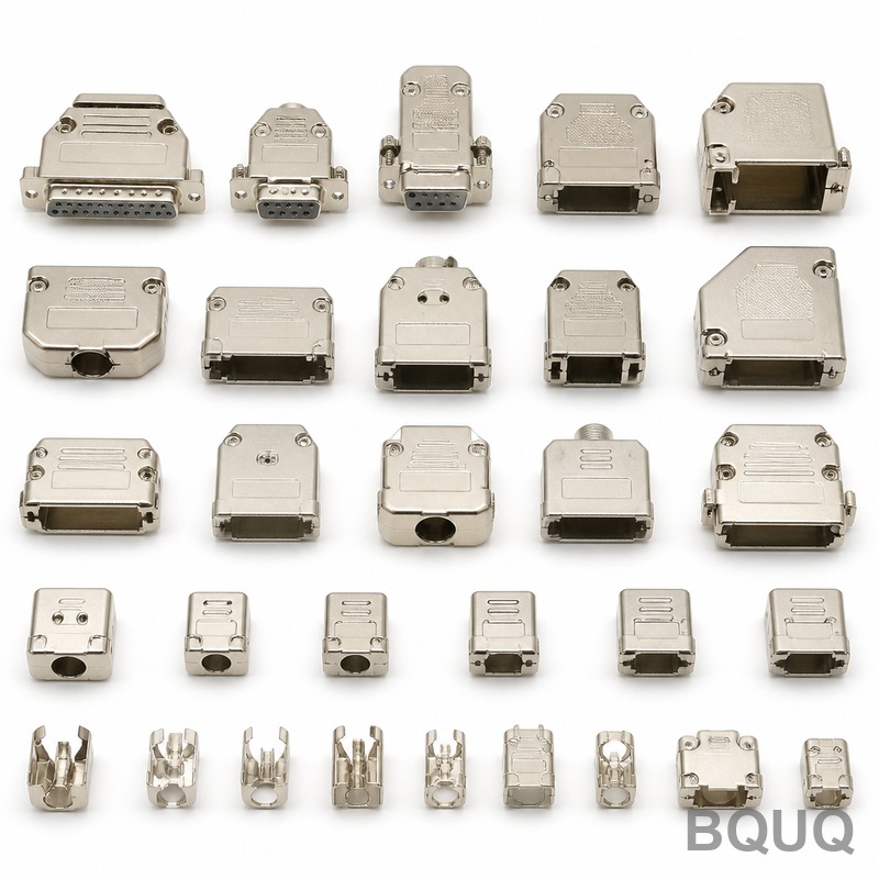
How to Design Parts for Metal Stamping: 10 Rules for Precision Manufacturing
Designing parts for metal stamping requires a fundamental shift from subtractive machining logic to high-volume progressive die thinking. In short, you must design for uniform wall thickness, generous bend radii, and consistent material flow to achieve tolerances of +/-0.05 mm at production speeds of 300 parts per minute. By following 10 specific design rules, you can reduce tooling costs by up to 30% and cut per-unit pricing by 15-20% compared to poorly optimized designs at BQUQ's Dongguan factory.
## Rule 1: Maintain Uniform Material Thickness Metal stamping does not cut away material like CNC machining; it displaces and shears it. If your part has a 2.0 mm thick flange transitioning to a 0.8 mm wall, the die will experience uneven stress distribution, leading to premature wear and micro-cracks in the tool steel. Design with a single, consistent sheet thickness across the entire part profile. For example, using 1.5 mm thick SPCC steel throughout allows you to hold flatness within 0.10 mm over a 100 mm length. If variable thickness is unavoidable, you must specify a coining or extruding operation, which adds 0.02 to 0.05 USD per stroke and increases tooling cost by 12-18%.
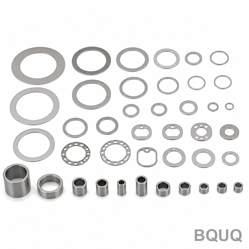
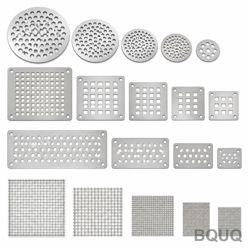
## Rule 2: Design Holes and Slots with Correct Minimum Sizes The minimum hole diameter you can reliably pierce is equal to the material thickness (T). For a 1.5 mm thick aluminum 5052 sheet, the smallest round hole is 1.5 mm diameter. For slots, the minimum width is 1.5T, and the length should be at least 2T. Punching holes smaller than the material thickness causes punch breakage, typically at a rate of 1 in 5,000 strokes, and increases die maintenance downtime. At BQUQ, we recommend hole diameters of 1.2T or larger for production runs exceeding 100,000 parts. For square holes, the corner radius must be at least 0.5T to prevent stress concentration and burr formation.
## Rule 3: Keep Minimum Distance Between Features The distance between the edge of a hole and the edge of the part must be at least 1.5T to avoid distortion of the adjacent material. If you place a 5 mm hole only 1 mm away from a 90-degree bend line, the hole will stretch and ovalize during the bending process, shifting its true position by up to 0.25 mm. We specify a minimum distance of 2.5T from the bend line to any hole or slot. For adjacent holes, the distance between their edges should be at least 2T. This preserves the structural integrity of the web and prevents tearing during the blanking operation.
## Rule 4: Optimize Bend Radii for Material Type A sharp internal bend radius of 0.1 mm creates high tensile stress on the outer surface, leading to cracking, especially in high-carbon steels or aluminum. The recommended minimum bend radius for mild steel (SPCC, Q235) is 0.5T to 1.0T. For aluminum 6061-T6, use a minimum bend radius of 1.5T to prevent fracture. For stainless steel 304, use 1.0T to 2.0T. Achieving a tighter radius than these values requires a secondary annealing process or hot stamping, which increases cycle time by 40% and energy costs by 0.01 USD per part. A larger bend radius also reduces springback; for a 90-degree bend in 2.0 mm steel, springback is typically 2-3 degrees, which can be compensated in the die design.
## Rule 5: Account for Springback in Material Selection Springback is the elastic recovery of the metal after the bending force is removed. For a 90-degree bend in 1.0 mm thick DP780 advanced high-strength steel, springback can be as high as 8-12 degrees, requiring over-bending in the die. This is a critical design rule: do not specify a final angle tolerance tighter than +/-0.5 degrees without stating the material grade and hardness. In production, we compensate for springback by either over-bending (adding a bend angle correction of 2-5 degrees) or by using a coining operation where the bottom of the die compresses the material to yield. Coining adds 15-20% to tooling cost but ensures dimensional stability within 0.1 degrees.
## Rule 6: Set Realistic Dimensional Tolerances Stamping is a high-speed process, but it does not achieve the tolerances of grinding or EDM. For blanking and piercing, standard tolerances are +/-0.10 mm for dimensions up to 25 mm, and +/-0.15 mm for dimensions from 25 to 100 mm. For bending, angular tolerances are typically +/-1 degree, and linear bend-to-bend dimensions are +/-0.15 mm. If you require +/-0.02 mm, the part must go through a secondary fine-blanking process, which increases cost by 300-400% and reduces press speed from 300 SPM to 40 SPM. At BQUQ, we recommend reserving tight tolerances only for critical mating surfaces and using +/-0.10 mm for general dimensions.
## Rule 7: Design for Burr Direction and Size Every stamped part has a burr on the cutting edge, typically 10% of the material thickness. For a 2.0 mm thick part, the burr is approximately 0.05 to 0.20 mm, depending on die clearance. You must specify the burr direction (up or down) on the drawing, as this affects assembly and safety. The standard die clearance is 5-8% of material thickness per side for soft steel and 3-5% for aluminum. To minimize burr height, use a fine-blanking process, which reduces burr to 0.01 mm but requires the material to be held by a V-ring. If burrs are unacceptable, specify a deburring operation, which adds 0.005 USD per part and 24 hours to lead time.
## Rule 8: Consider Material Grain Direction Rolled metal sheets have a grain direction from the rolling process. Bends made parallel to the grain direction are more prone to cracking than bends made perpendicular to the grain. For example, bending 1.5 mm thick cold-rolled steel parallel to the grain can reduce the minimum bend radius from 0.75 mm to 1.5 mm. You should specify the grain direction on the part drawing, especially for structural components. For high-volume parts, we recommend orienting the strip layout in the die so that critical bends are perpendicular to the grain. This does not add cost but significantly improves part strength and reduces scrap rates by up to 5%.
## Rule 9: Use Standard Hole and Feature Sizes Tooling costs are directly proportional to the number of custom punches and dies. A standard round punch for a 3.0 mm hole costs 30 USD, while a custom hexagonal punch costs 120 USD and requires 3 weeks of lead time. Design all holes using standard metric diameters (1.0, 1.2, 1.5, 2.0, 2.5, 3.0, 3.5, 4.0, 5.0, 6.0 mm) and standard thread sizes (M2, M2.5, M3, M4, M5, M6) for tapped holes. For self-clinching nuts, use standard punch sizes (M3, M4, M5, M6) which correspond to specific mounting hole diameters (4.2 mm for M3, 5.4 mm for M4). Standardizing features reduces die manufacturing time by 15% and allows for faster replacement of worn punches.
## Rule 10: Design for Progressive Die Feasibility If your part volume exceeds 50,000 units per year, a progressive die is the most economical choice. This requires the part to be designed with a consistent strip width and a carrier strip that connects the part to the coil. The part must be indexable, meaning it can be moved through multiple stations without rotation. The maximum part size for a progressive die at BQUQ is 300 mm x 300 mm, with a material thickness range of 0.1 mm to 6.0 mm. For parts with complex 3D forms, consider a compound die or a transfer die system. A progressive die tool for a simple bracket costs 8,000 to 15,000 USD, while a complex die for a heat sink clip costs 25,000 to 40,000 USD. If the part cannot be designed for stripping, it will require a more expensive multi-slide or four-slide machine.
Cost and Lead Time Comparison Table
| Part Feature | CNC Machining Cost per Unit | Stamping Cost per Unit | Stamping Tooling Cost | Stamping Lead Time (First Article) | Production Speed (Parts/Hour) |
| Simple flat bracket 100x50x2mm, 4 holes | 12.50 USD | 0.85 USD | 8,000 USD | 25 days | 3,600 |
| Bent L-bracket with 2 holes, 1.5mm steel | 18.00 USD | 1.20 USD | 12,500 USD | 30 days | 2,400 |
| Heat sink clip, 0.8mm spring steel, 3 bends | 25.00 USD | 1.80 USD | 18,000 USD | 35 days | 1,800 |
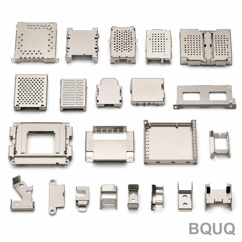
| Complex EMI shield, 0.5mm, 6 bends, 10 holes | 45.00 USD | 3.20 USD | 28,000 USD | 45 days | 1,200 |
| High-volume connector terminal, 0.2mm copper | N/A (not feasible) | 0.02 USD | 35,000 USD | 50 days | 12,000 |
Practical Recommendations for Your Design Package
When you send a stamped part design to BQUQ, include the following data to ensure a fast and accurate quote. First, specify the material grade and hardness, such as SPCC (Rockwell B 60), SUS304 (Rockwell B 85), or C17200 beryllium copper. Second, provide a 3D STEP file and a 2D PDF with GD&T calls. Third, state the annual volume and the required tolerances for critical dimensions. For prototype validation, we recommend a soft tool using hardened tool steel (SKD11) with a hardness of HRC 58-62, which lasts for 50,000 to 100,000 strokes. For production, we use a hard tool with carbide inserts (HRC 70-72) that can produce over 2 million parts before major maintenance. We also recommend a surface finish of Ra 0.8 micrometers for the mating surface, which is achievable with a secondary grinding operation.
FAQ-Style Design Tips for Metal Stamping
What is the maximum part size for stamping? At BQUQ, our largest press has a capacity of 400 tons, allowing us to stamp parts up to 1200 mm in length and 800 mm in width. The material thickness limit is 8.0 mm for steel and 6.0 mm for stainless steel. For parts larger than this, we recommend switching to a stamping and welding assembly approach to reduce press tonnage requirements.
Can I stamp threads into a part? Yes, you can use a tapping operation inside the progressive die. This is cost-effective for volumes above 50,000 parts. For example, tapping an M4 hole in 2.0 mm steel adds 0.03 USD per part. However, the minimum recommended thread engagement is 1.5 times the thread pitch, so a 2.0 mm sheet is not suitable for M4 threads (pitch of 0.7 mm) without using a self-clinching nut.
How does material thickness affect pricing? Thinner materials (0.1 mm to 0.5 mm) are harder to feed and require careful die alignment, increasing setup time by 30%. Thicker materials (above 3.0 mm) require higher press tonnage, which increases the cost per stroke. The most economical stamping range is 0.8 mm to 2.5 mm, where press speeds are maximum and tool wear is minimal.
What is the minimum order quantity for stamping? For standard parts, the MOQ is 5,000 pieces. For complex progressive die parts, the MOQ is 10,000 pieces to amortize the tooling cost. If you need 500 parts for a pilot run, we can use a soft aluminum die to reduce tooling cost by 50%, but the tool life will be limited to 5,000 strokes.
## Conclusion Designing for metal stamping is about respecting the physics of high-speed deformation and the economics of tooling amortization. By adhering to the 10 rules above, you ensure that your part is manufacturable, cost-effective, and reliable at scale. The key takeaway is to maintain uniform thickness, keep features at safe distances, and specify realistic tolerances that match the stamping process capability. At BQUQ, we have applied these principles for 20 years to produce heat sinks, springs, and stamped enclosures for global OEMs. We provide a 12-hour quoting service for all stamped part inquiries. Email your 3D file to sc@bquq.com or message us on WhatsApp at +86 13713157787. Visit www.bquq.com to download our design guide and tolerance chart.


