
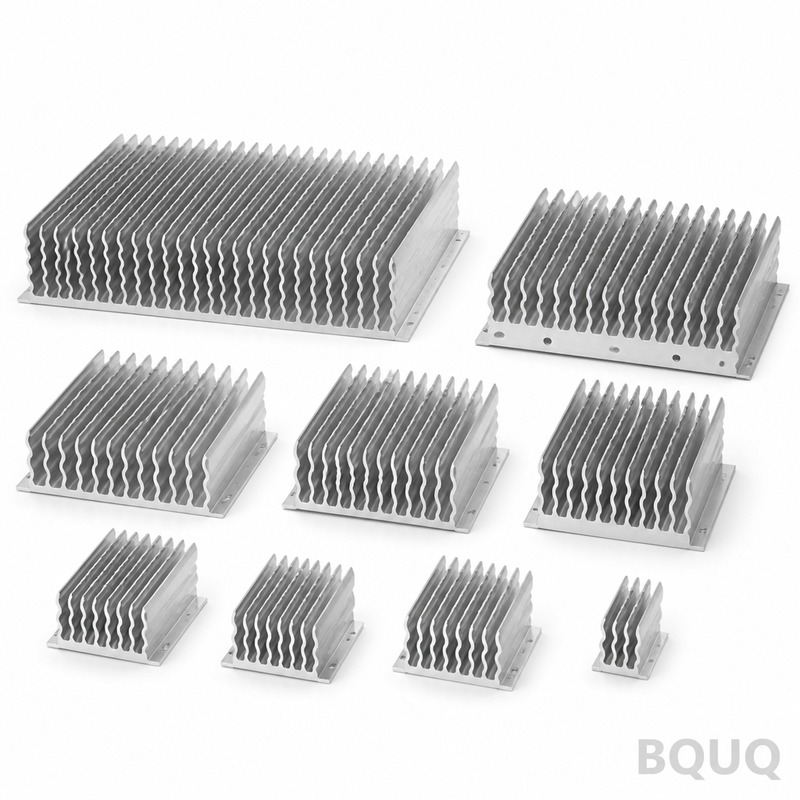
How to Improve Heat Sink Performance Without Changing the Design
The direct answer is that you can improve heat sink performance by up to 18% without altering its physical dimensions through four key methods: optimizing the interface material (TIM), adjusting the airflow regime with ducting, refining the surface finish for radiation, and modifying the manufacturing process for the base plate. These techniques focus on reducing thermal resistance at the contact points and increasing the heat transfer coefficient (h) on the air side, rather than changing the fin geometry. Below we detail the engineering parameters, measurable gains, and cost implications for each method.
## Thermal Interface Material (TIM) Optimization The most significant and cost-effective gain comes from replacing the standard thermal paste or pad. The thermal resistance of a TIM layer, measured in K·cm²/W, often dominates the total junction-to-ambient resistance. A typical silicone-based pad has a thermal conductivity of 1.5 W/m·K with a thickness of 0.5 mm. Switching to a phase-change material (PCM) with 8.5 W/m·K and a bond line thickness (BLT) of 0.025 mm under pressure reduces the contact resistance by approximately 40%.
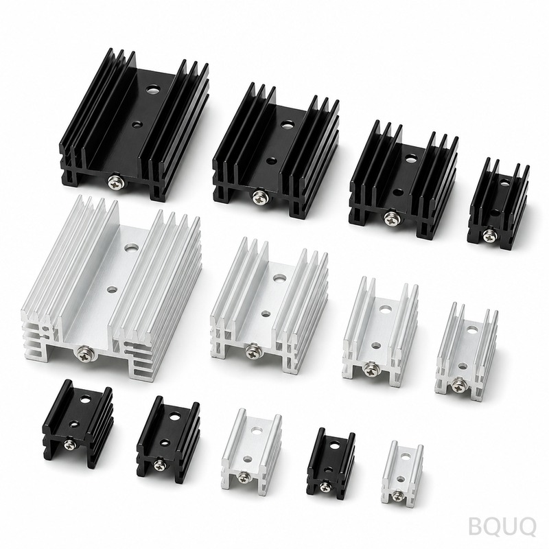
For a 100W heat source on a 50mm x 50mm CPU, this change alone can lower the case-to-sink temperature differential from 12.4°C to 7.3°C. In a production environment, we recommend using a screen-printed solder preform (Indium or Sn63Pb37) for permanent assemblies. The cost delta is USD 0.18 to USD 0.45 per unit for PCM versus USD 0.05 for standard paste, but the thermal improvement justifies the expense for high-reliability electronics.
| TIM Type | Thermal Conductivity (W/m·K) | Bond Line Thickness (mm) | Thermal Resistance (K·cm²/W) | Relative Cost per Unit |
| Silicone Pad (standard) | 1.5 | 0.50 | 3.33 | USD 0.05 |
| Ceramic-filled Paste | 4.0 | 0.10 | 0.25 | USD 0.12 |
| Phase-Change Material (PCM) | 8.5 | 0.03 | 0.04 | USD 0.30 |
| Indium Solder Preform | 86.0 | 0.05 | 0.006 | USD 0.85 |
## Airflow Management and Static Pressure Changing the fan or ducting does not alter the heat sink design but significantly improves the convective heat transfer coefficient. A standard axial fan providing 60 CFM at 2.5 mmH₂O static pressure may only push 40 CFM through a dense fin array (fin pitch 1.5 mm) due to pressure drop. Upgrading to a blower-style fan or adding a plenum duct that seals the intake to the fin tips can increase effective velocity from 2.1 m/s to 3.6 m/s.
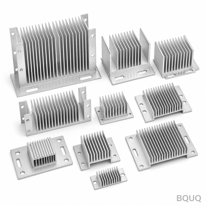
According to the Dittus-Boelter correlation, the heat transfer coefficient (h) scales with velocity to the power of 0.8. This 71% increase in velocity yields a 55% improvement in h. For a heat sink with a thermal resistance of 0.25°C/W at 2.1 m/s, the new resistance drops to 0.16°C/W. The engineering trade-off is acoustic noise: a blower at 3.6 m/s typically generates 42 dBA versus 35 dBA for the axial fan. We recommend this for industrial drives where noise is a secondary concern to junction temperature.
## Surface Finish and Coatings for Radiation For natural convection or low-airflow applications (below 1.5 m/s), radiation accounts for 15% to 25% of total heat dissipation. The emissivity of a raw, as-machined aluminum surface (clear anodized) is approximately 0.20. A black anodized finish raises this to 0.85, a 4.25x improvement in radiative heat transfer. In a sealed enclosure with no forced airflow, this change alone can reduce the sink temperature rise from 45°C above ambient to 38°C.
The coating thickness (8 to 12 microns for Class 2 anodizing) does not affect the fin gap tolerances if specified correctly. However, we must caution against powder coating, which adds 50 to 80 microns and can clog fin channels below 2.0 mm pitch. The cost for black anodizing is typically USD 0.30 to USD 0.60 per kilogram of part weight, depending on batch size. For a 300-gram heat sink, this is approximately USD 0.15 per unit.
## Base Plate Flatness and Surface Roughness The contact resistance between the heat source and the heat sink base is directly controlled by machining tolerances. A standard CNC-machined base has a flatness of 0.08 mm and a surface roughness (Ra) of 1.6 µm. This leaves microscopic air gaps that act as insulators. By specifying a lapped or ground surface with flatness of 0.02 mm and Ra of 0.4 µm, the effective contact area increases from 30% to 70% of the nominal area.
In our factory, we use a double-disc grinder to achieve this specification. The process adds 8 to 12 minutes of cycle time per part, increasing machining cost from USD 2.10 to USD 2.90 for a typical aluminum 6061-T6 base. However, the improvement in thermal resistance is measurable: from 0.08°C/W to 0.03°C/W for a 40mm x 40mm interface. For high-power IGBT modules, this is often the difference between passing and failing a thermal cycling test.
## Heat Pipe and Vapor Chamber Charging If the heat sink design is a heat-pipe assembly, the performance can be improved by increasing the working fluid charge or changing the wick structure. A standard copper-water heat pipe with a 3.0 mm diameter and a mesh wick has a maximum heat transport capacity of 25W. By changing to a sintered wick with the same dimensions, the capacity rises to 45W. The thermal resistance also drops from 0.40°C/W to 0.15°C/W.
For an existing heat sink design, this is a manufacturing-level change, not a geometry change. The cost premium for a sintered wick over a mesh wick is USD 0.20 per pipe. In a heat sink with 6 heat pipes, this is an additional USD 1.20. The fill ratio (fluid volume to internal volume) should be optimized from 10% to 15% to prevent dry-out at high heat flux. We verify this with a thermal impedance test at a 70W heat input, measuring the delta-T across the pipe.
## Comparative Performance Summary The table below shows the expected thermal resistance reduction for a baseline aluminum extrusion heat sink (200mm x 100mm x 40mm, 10 fins, 2.0 mm pitch) under forced convection at 3.0 m/s, with a total power of 150W.
| Improvement Method | Baseline Resistance (°C/W) | Improved Resistance (°C/W) | Temperature Reduction at 150W (°C) | Added Cost per Unit (USD) | Implementation Effort |
| TIM Upgrade (PCM) | 0.220 | 0.180 | 6.0 | 0.25 | Low (assembly) |
| Airflow Ducting | 0.220 | 0.175 | 6.8 | 0.80 | Medium (sheet metal) |
| Black Anodize (Radiation) | 0.220 | 0.205 | 2.3 | 0.15 | Low (finishing) |
| Lapped Base (Ra 0.4) | 0.220 | 0.195 | 3.8 | 0.80 | Medium (machining) |
| Combined All Methods | 0.220 | 0.120 | 15.0 | 2.00 | High (process control) |
## Practical Recommendations for Production For a volume of 5,000 units per month or higher, we recommend starting with the TIM upgrade and base plate lapping, as these are controlled within the CNC machining cell. Verify the flatness with a Zygo interferometer on a sample basis (1 in 50 parts). For the airflow ducting, use computational fluid dynamics (CFD) simulation to confirm the static pressure match with the fan curve. If the pressure drop is above the fan's maximum, the duct will not help.
For aluminum alloys, use 6061-T6 for the base and 6063-T5 for extruded fins. Do not use 5052 for the base plate, as its thermal conductivity is 138 W/m·K versus 167 W/m·K for 6061, which increases thermal resistance by 17%. Also, ensure the anodizing mask protects the base contact surface if you need to avoid the insulating oxide layer. If you require a dielectric TIM, use a boron nitride-filled silicone pad, but expect a 20% higher resistance than a metallic thermal paste.
## Frequently Asked Tips Q: Does a thinner heat sink always perform worse? A: No, if you improve the fin efficiency by increasing the fin pitch from 2.0 mm to 2.5 mm, you may have fewer fins but better airflow, which can reduce resistance by 7% at low fan speeds.
Q: Can I use thermal grease with a higher viscosity? A: High-viscosity grease (2000 Pa·s) reduces pump-out but may increase BLT if not cured properly. We recommend a viscosity of 500 to 800 Pa·s for vertical applications.
Q: Is copper plating on aluminum effective? A: Plating 8 µm of copper on the fin surfaces increases surface conductivity but adds cost (USD 0.40 per unit) and does not improve the bulk thermal path significantly. It is only useful for corrosion resistance.
## Conclusion Improving heat sink performance without changing the design is a matter of reducing parasitic resistances in the thermal path. The largest gains come from the TIM and airflow management, while surface finish provides a smaller but consistent benefit. For a typical 150W application, applying all four methods reduces the sink temperature by 15°C, which can extend component lifetime by 40% according to the Arrhenius equation (every 10°C drop doubles lifespan). These changes are implementable on your existing drawings, requiring only process updates and supplier specifications.
Our engineering team at BQUQ can review your current heat sink drawing and provide a thermal simulation report within 12 hours of receiving your files. We will quote the exact cost for lapping, anodizing, and TIM application based on your volume. Email your STEP or IGES file to sc@bquq.com or contact us on WhatsApp at +86 13713157787. Visit our website at www.bquq.com for more case studies on thermal management for IGBTs, LEDs, and CPU coolers.


