
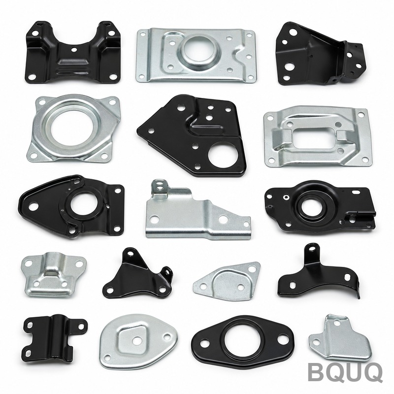
How to Inspect Stamped Parts: Dimensional and Visual QC Methods
The most effective inspection strategy for stamped parts combines 100% automated visual inspection with statistical dimensional sampling, using calibrated tools like CMMs and optical comparators to verify tolerances down to ±0.05 mm. For high-volume production, you should implement in-process checks every 2 hours for critical dimensions and a first-article inspection (FAI) report before mass production begins. This dual approach catches cosmetic defects that affect assembly fit while ensuring geometric compliance with your engineering drawings.
What Are the Two Main Categories of Stamped Part Inspection?
Stamped part inspection splits into dimensional QC, which verifies geometric features like hole diameters, bend angles, and flatness, and visual QC, which assesses surface finish, burr height, and coating integrity. Dimensional inspection relies on contact or optical measurement tools to confirm the part matches the CAD model within specified tolerances, typically ±0.05 mm to ±0.13 mm for standard stamping. Visual inspection, often automated with machine vision systems, detects scratches, dents, discoloration, and burrs that could cause functional issues or customer rejection. Both categories must be performed at defined intervals: dimensional checks during setup and every 4 hours of production, while visual checks run continuously on 100% of parts when using automated systems.
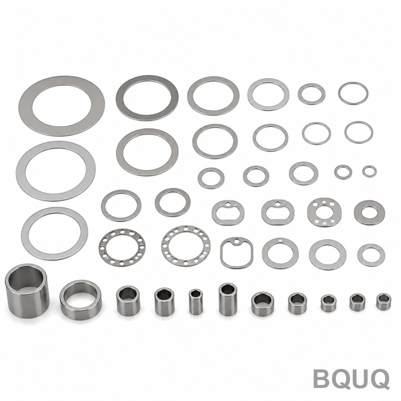
Which Dimensional Measurement Tools Are Required for Stamped Parts?
Your tool selection depends on the tolerance class and production volume. For critical dimensions with tolerances under ±0.05 mm, use a coordinate measuring machine (CMM) with a resolution of 0.001 mm, which offers accuracy of ±0.002 mm per axis. For medium-volume runs, optical comparators with 10x to 50x magnification allow quick 2D profile checks against an overlay chart, achieving repeatability of ±0.01 mm. Calipers and micrometers are sufficient for non-critical features with tolerances above ±0.1 mm, offering readings accurate to ±0.02 mm and ±0.005 mm respectively. For hole positions, pin gauges provide a go/no-go check within 0.01 mm increments, while a surface roughness tester measures Ra values from 0.2 to 3.2 micrometers, which is critical for sealing surfaces and bearing seats.
How Do You Perform a First Article Inspection for Stamped Parts?
A first article inspection (FAI) is a complete dimensional and visual verification of the first production part against all drawing requirements, and it must be performed before releasing a new or modified tool for mass production. Start by reviewing the part drawing and identifying all characteristics: critical dimensions, material thickness, surface finish, and edge conditions. Measure every dimension using a CMM for 3D features, an optical comparator for 2D profiles, and a hardness tester if the drawing specifies a Rockwell or Vickers hardness range. Record the results on an AS9102 or PPAP form, noting the actual measured value, the tolerance range, and the measurement tool used, then submit this document to your customer for approval. A complete FAI typically takes 4 to 8 hours for a part with 20 to 50 dimensions, including the creation of a ballooned drawing that numbers each characteristic for traceability.
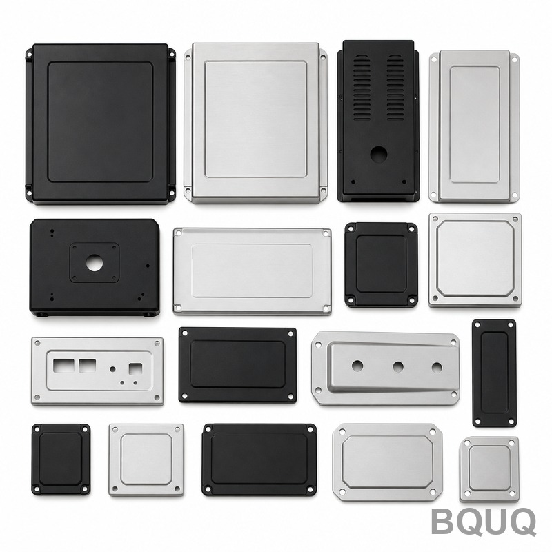
What Are the Key Visual Defects to Check During Stamped Part Inspection?
Visual inspection must target six primary defect categories: burrs, scratches, dents, discoloration, cracks, and coating defects. Burr height should not exceed 10% of material thickness for most applications, for example, a 1.5 mm thick steel part allows a maximum burr of 0.15 mm, which you can verify using a burr gauge or a dial indicator with a flat base. Scratches deeper than 0.05 mm or longer than 3 mm are typically rejected for exposed surfaces, and you can measure scratch depth with a stylus profilometer. Dents are evaluated by diameter and depth: any dent larger than 1 mm in diameter and 0.1 mm deep on a visible surface fails inspection. Cracks, which often appear near bend radii or stamped holes, are detected using dye penetrant testing on a sample of 5 parts per batch, especially when forming high-strength steels above 590 MPa. Discoloration from overheating, such as blue or brown stains on stainless steel, indicates excessive friction and requires tooling review.
When Should You Use Automated Vision Systems Versus Manual Inspection?
Automated vision systems are justified when production volume exceeds 50,000 parts per month or when defect rates must stay below 100 parts per million (PPM). A typical vision system with a 5-megapixel camera, telecentric lens, and programmable logic controller (PLC) can inspect 60 to 120 parts per minute, checking dimensions, hole presence, and surface defects simultaneously, with a false rejection rate below 1%. Manual inspection is appropriate for low-volume runs under 10,000 parts, prototype batches, or parts with complex 3D geometries that require operator judgment, but it only achieves 80% to 90% defect detection efficiency due to human fatigue. For maximum reliability, use a hybrid approach: machine vision for 100% in-line checks and manual audit of 5 parts per hour for features the camera cannot assess, such as internal threads or deep recesses.
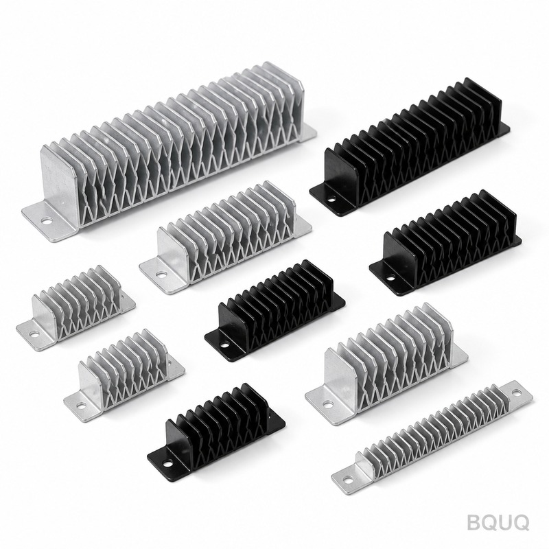
How Do You Establish a Statistical Process Control Plan for Stamped Parts?
A statistical process control (SPC) plan uses sampling and control charts to detect process drift before non-conforming parts are produced. For each critical dimension, take a sample of 5 consecutive parts every 2 hours and measure the feature, then plot the average and range on an X-bar and R chart with control limits set at three standard deviations from the process mean. For example, if a hole diameter has a spec of 6.00 mm ± 0.05 mm, the control limits might be 6.01 mm and 5.99 mm, and any point outside these limits triggers an immediate process stop and tool inspection. Calculate the process capability index (Cpk) after 25 samples; a Cpk of 1.33 or higher is required for most automotive and electronics applications, while 1.67 is preferred for safety-critical parts. If Cpk falls below 1.33, the tooling must be reconditioned or the process parameters, such as press speed (typically 30 to 80 strokes per minute) and blank holder force, must be adjusted.
What Are the Typical Pass-Fail Criteria for Dimensional and Visual Inspection?
| Inspection Type | Feature Checked | Pass Criteria | Measurement Tool | Sampling Frequency |
| Dimensional | Hole diameter | Within ±0.05 mm of nominal | Pin gauge or CMM | 5 parts every 2 hours |
| Dimensional | Bend angle | ±0.5 degrees | Optical comparator | 5 parts every 4 hours |
| Dimensional | Flatness | Within 0.1 mm over 100 mm length | Surface plate with dial indicator | First article and every 8 hours |
| Visual | Burr height | Maximum 10% of material thickness | Burr gauge or microscope | 100% automated or 10% manual |
| Visual | Scratch depth | Maximum 0.05 mm on exposed surfaces | Stylus profilometer | 5 parts per batch |
| Visual | Coating adhesion | No peeling after tape test (ASTM D3359) | Cross-cut tape kit | 1 part per batch |
| Material | Hardness | Within HRC 30-35 for spring steel | Rockwell hardness tester | 3 parts per heat lot |
FAQ
What Is the Difference Between Dimensional and Visual Inspection?
Dimensional inspection measures physical attributes like length, diameter, and angle using calibrated instruments to verify geometric conformance, while visual inspection evaluates surface condition, color, and edge quality without altering the part. Both are required for complete QC, as a part can be dimensionally correct but cosmetically unacceptable, or visually perfect but out of tolerance.
How Often Should Stamped Parts Be Inspected During Production?
In-process inspection should occur at a minimum of every 2 hours for critical dimensions and every 4 hours for non-critical features, with 100% visual inspection if automated systems are installed. Additionally, a full dimensional audit of 5 parts should be performed at the start of each shift and after any tool adjustment or material change.
Can a Stamped Part Be Rejected for Visual Defects Only?
Yes, visual defects alone are a valid reason for rejection, especially for exposed or decorative parts, even if all dimensions are within tolerance. Deep scratches, dents, and burrs can affect assembly fit, cause stress concentrations, or lead to corrosion, and most customer specifications include visual acceptance criteria that are contractually binding.
What Is the Cost of Setting Up a Basic Stamped Part Inspection Station?
A basic manual inspection station with calipers, micrometers, pin gauges, a surface plate, and a burr gauge costs approximately USD 2,000 to 5,000. Adding an optical comparator increases the cost by USD 15,000 to 30,000, while a full CMM system ranges from USD 50,000 to 150,000, excluding software and operator training.
When Should You Perform a Capability Study on a Stamped Part?
Perform a capability study after the first article inspection passes and before full-rate production begins, using a minimum of 25 to 30 consecutive parts from the same tool and material batch. Run the study again whenever the tool is reworked, the material supplier changes, or the press settings are significantly altered, as these factors directly affect dimensional stability.
Which Stamped Part Features Are Hardest to Inspect Accurately?
The hardest features to inspect are small holes below 1 mm diameter, internal threads, deep counterbores, and complex 3D bend contours, as they require specialized probes or non-contact sensors. These features often need a CMM with a micro-probe or a white light scanner, which adds 30% to 50% more inspection time compared to standard features.
Conclusion
Effective inspection of stamped parts is not a single activity but a layered system of dimensional measurement, visual assessment, and statistical monitoring that must be tailored to your tolerance requirements and production volume. By combining first article inspections, regular SPC sampling, and automated vision for high-volume lines, you can maintain defect rates below 100 PPM and ensure every shipment meets specification. At BQUQ, our quality team applies these exact methods on every stamping project, using calibrated CMMs and in-house vision systems to deliver parts with 99.8% on-time quality performance. For a free feasibility review of your stamped part drawing and a detailed inspection plan, contact us today and receive a quotation within 12 hours.
Email: sc@bquq.com
WhatsApp: +86 13713157787
www.bquq.com
Related Articles
- Multi-Physics Coupled Failure Mechanisms and Systematic Prevention Strategies in Stamping Processes
- Intelligent online inspection and closed-loop quality control: creating a zero-defect production line for stamped parts
- Stamping digital factory and simulation-driven design: from virtual prototype to digital twin operation


