
How to Specify Springs on Drawings: GD&T and Critical Dimensions
To specify a spring correctly on an engineering drawing, you must define the wire diameter, mean coil diameter, free length, number of active coils, spring rate, and material, then apply GD&T to control the spring's axis straightness and end flatness. A complete spring specification also requires tolerances on load at a specific height, solid height, and direction of helix, with GD&T datum features established from the spring's bearing surfaces. This article provides the exact dimensioning and tolerancing methodology used by BQUQ's 20-year precision manufacturing team to ensure springs are produced correctly on the first attempt.
What Are the Critical Dimensions That Must Be Present on a Spring Drawing?
Every spring drawing must include the wire diameter (d), mean coil diameter (D), outside diameter (OD), inside diameter (ID), free length (L0), solid height (Ls), and total number of coils (Nt). You must also specify the spring rate (k) in N/mm or lbf/in, the maximum deflection, and the load at a specific test height (P1 and P2). Without these nine parameters, the spring cannot be manufactured or inspected, as each dimension directly affects the stress, fatigue life, and installed height of the component.
How Should GD&T Be Applied to a Spring's Axis and End Surfaces?
The spring's axis must be controlled with a cylindricity or straightness tolerance relative to a datum axis established from the two end coils. Apply a perpendicularity tolerance of 0.5% to 1% of the free length between the end planes and the spring axis, using a datum reference frame from the ground end surfaces. For critical applications, specify a total runout of 0.25 mm on the OD relative to the datum axis to ensure the spring does not bind or generate vibration in the assembly.
Which Datum Features Are Most Important for Spring Function?
The two ground end surfaces must be designated as Datum A and Datum B, as they define the spring's orientation in the assembly. These surfaces must be parallel to each other within 0.1 mm for compression springs, and the flatness of each end must not exceed 0.05 mm. When the spring has close-ground ends, the first and last coils are considered part of the datum features, and their angular orientation relative to the spring axis must be specified if the spring has a specific index position requirement.
How Do You Define Spring Rate and Load Tolerances on a Drawing?
The spring rate tolerance is typically ±5% of the nominal value, but for precision applications, BQUQ can hold ±3% through load testing at two specified heights. You must specify the load at 50% and 75% of the maximum deflection, with tolerances of ±10% for standard springs and ±5% for critical safety components. The drawing should state the test condition, including the preload height and the rate of load application, to ensure the manufacturer and customer inspect the spring identically.
What Tolerances Are Achievable for Wire Diameter and Coil Diameter?
Wire diameter tolerance follows the ASTM A228 or EN 10270 standards, with typical values of ±0.01 mm for wire under 1.0 mm and ±0.02 mm for wire from 1.0 mm to 5.0 mm. The mean coil diameter tolerance is ±0.1 mm for springs with an OD under 20 mm, and ±0.2 mm for larger diameters, provided the spring index (D/d) is between 4 and 12. For high-volume stamping or coiling processes, BQUQ holds a Cpk of 1.33 or greater on all critical dimensions.
How Should Free Length and Solid Height Be Dimensioned and Toleranced?
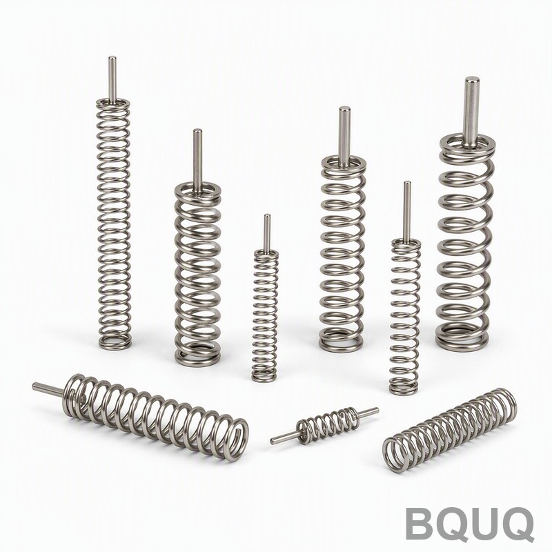
Free length must be dimensioned as a basic dimension with a tolerance of ±0.5% of the nominal length, but never less than ±0.2 mm. Solid height must be specified as a maximum value, calculated as Nt multiplied by the maximum wire diameter, and it must be verified with a 0.1 mm feeler gauge between coils when fully compressed. The drawing must also note the maximum allowable set or relaxation after compression to solid height, typically less than 2% of the free length.
Why Is the Direction of Helix and End Configuration Critical to Specify?
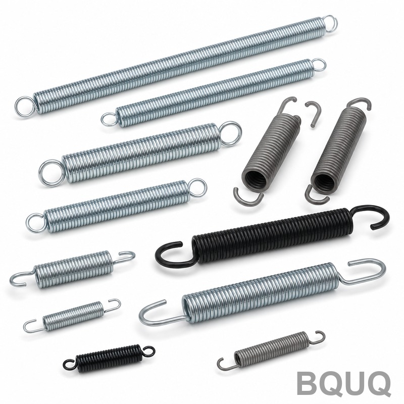
The direction of helix, either right-hand or left-hand, must be stated on the drawing because it affects how the spring interacts with mating threaded components and adjacent coils. The end configuration must be specified as plain, plain-ground, squared, or squared-and-ground, as this changes the number of inactive coils and the effective spring rate. For springs in dynamic applications, the end type also determines stress concentration factors, with squared-and-ground ends being mandatory for springs cycled above 100,000 cycles.
Data Table: Recommended Spring Specification Tolerances for CNC Coiling and Stamping
| Dimension Parameter | Standard Tolerance | Precision Tolerance | Inspection Method |
| Wire Diameter (d) | ±0.02 mm | ±0.01 mm | Micrometer, 3-point |
| Mean Coil Diameter (D) | ±0.20 mm | ±0.10 mm | Optical comparator |
| Free Length (L0) | ±0.50% | ±0.20% | Height gauge, CMM |
| Solid Height (Ls) | Max value only | Max value +0.1 mm | Compression test |
| Spring Rate (k) | ±5% | ±3% | Load-deflection test |
| Load at Test Height | ±10% | ±5% | Force gauge |
| Perpendicularity of Ends | 1% of L0 | 0.5% of L0 | Surface plate, indicator |
| Flatness of End Coil | 0.10 mm | 0.05 mm | Feeler gauge |
| Surface Finish (Ra) | 1.6 µm | 0.8 µm | Profilometer |
What Information Should Be Included in the Drawing Notes for Heat Treatment and Coating?
The drawing notes must specify the material grade, such as ASTM A228 music wire or EN 10270-1 oil-hardened wire, along with the required tensile strength range. For springs that require stress relief, specify the heat treatment temperature, typically 200°C to 300°C for 30 minutes, and for pre-stressing or shot peening, note the intensity in Almen scale A. Corrosion protection must be specified as zinc plating with a thickness of 8 to 12 µm, or as a phosphate coating, and the drawing must state whether hydrogen embrittlement relief baking at 190°C for 4 hours is required.
How Do You Specify Fatigue Life and Maximum Stress on a Spring Drawing?
The maximum operating stress should be stated as a percentage of the material's tensile strength, typically 45% for static applications and 30% for dynamic applications. For springs designed for more than 10 million cycles, the drawing must specify a shot-peening process and a fatigue test requirement with a minimum cycle count. The drawing should also include the maximum allowable stress at solid height, which should not exceed 60% of the tensile strength to prevent permanent set.
Can You Use GD&T Position Tolerances for Spring Holes and Mounting Features?
Yes, if the spring mounts into a bore or over a rod, you can apply a position tolerance of 0.1 mm to the mating diameter relative to the same datum features used for the spring ends. The recommended clearance between the spring OD and the bore ID is 2% to 5% of the spring OD to prevent buckling and frictional wear. For precision assemblies, apply a concentricity tolerance of 0.15 mm between the spring's mean diameter and the mounting feature's axis to ensure consistent load distribution.
FAQ Section
What Is the Difference Between Squared and Squared-and-Ground Ends?
Squared ends are closed and compressed but not ground flat, while squared-and-ground ends have the last coil ground flat to provide a perpendicular bearing surface. Squared-and-ground ends are required for most compression springs because they reduce buckling and provide stable load transmission.
How Many Active Coils Should Be Specified for a Compression Spring?
The number of active coils excludes the end coils that are closed and ground, and it directly determines the spring rate. For a spring with squared-and-ground ends, subtract two coils from the total number to get the active coil count.
What Is the Minimum Spring Index Recommended for Manufacturing?
The spring index, calculated as the mean coil diameter divided by the wire diameter, should be between 4 and 12 for economical manufacturing. A spring index below 4 causes excessive tool wear, while an index above 12 makes the spring prone to buckling.
When Should a Spring Drawing Specify a Load Test Instead of a Spring Rate?
A load test at a specific height is preferred when the spring is installed in a confined space and the force at a known deflection is critical. The spring rate alone is insufficient for assembly because the free length variation can shift the operating point.
Which Surface Finish Is Required for High-Fatigue Springs?
High-fatigue springs require a surface finish of Ra 0.8 µm or better, achieved through grinding or shot peening. Any surface defect such as a scratch or pit can initiate a crack, so the drawing must specify a maximum defect depth of 0.05 mm.
How Is the Direction of Helix Indicated on a Drawing?
The direction of helix is indicated with a note stating "Right-Hand Helix" or "Left-Hand Helix," and it is visible by looking at the end of the spring. If not specified, most manufacturers default to right-hand helix, but this should never be left to assumption.
Can a Spring Drawing Use a 3D Model Instead of 2D GD&T?
A 3D model is acceptable as the master definition, but the GD&T tolerances and critical dimensions must be explicitly called out on a 2D drawing or in a PMI (Product Manufacturing Information) table. The 3D model alone is insufficient because it does not convey tolerances for spring rate, load, or heat treatment.
Conclusion
Specifying springs on drawings requires a clear, complete set of dimensions, tolerances, and material notes that leave no room for interpretation. By including the critical dimensions, GD&T controls, and process requirements detailed in this article, you ensure that your spring supplier produces a component that meets your functional requirements without costly delays. BQUQ provides engineering support to review your spring drawings and offers a 12-hour quoting service for custom springs, metal stamping, and CNC machined parts.
For a rapid quotation or drawing review, contact our engineering team at sc@bquq.com or via WhatsApp at +86 13713157787. Visit our website at www.bquq.com to upload your drawings and receive a detailed quote within 12 hours.
Related Articles
- Size control and online intelligent detection technology of precision spring
- Hardware spring fatigue failure analysis and life prediction technology
- In-depth analysis of technology and process in the hardware spring industry in 2026: a full-dimensional interpretation of high stress, functional integration and engineering certification


