
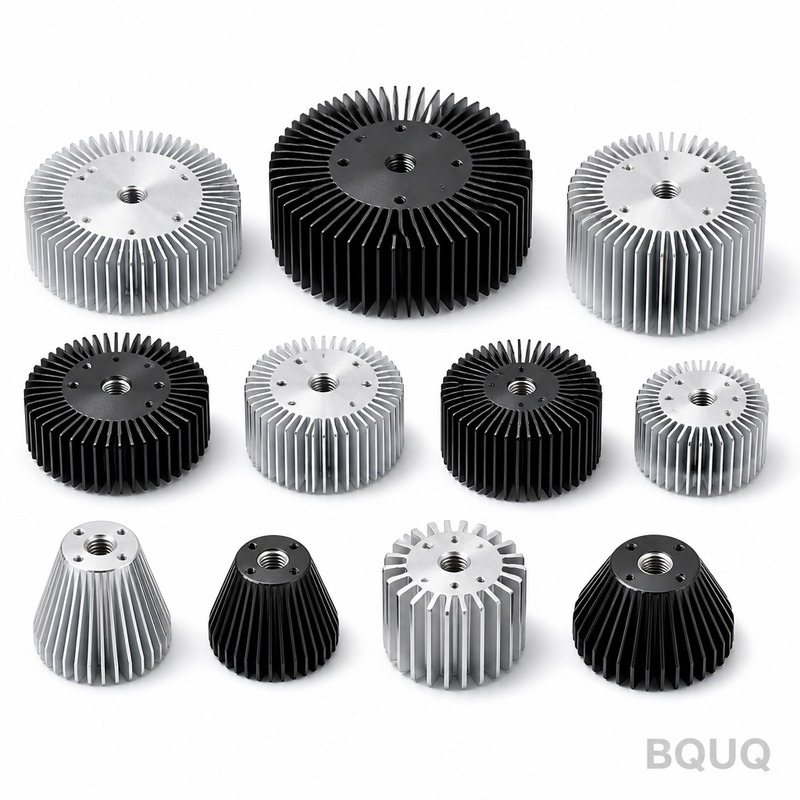
How to Test a Heat Sink: Measuring Thermal Resistance in Practice
The most direct method to test a heat sink is to measure its thermal resistance (Rth) in °C/W by applying a known power load to a heated die, mounting the heat sink under controlled airflow, and measuring the temperature difference between the heat sink base and the ambient air. Specifically, you calculate Rth = (Tjunction – Tambient) / Power, using thermocouples and a regulated DC power supply to achieve accuracy within ±0.5°C. For production validation at BQUQ, we recommend the ASTM D5470 standard methodology adapted for convective cooling, which yields repeatable results with a variance of less than 3% across consecutive test runs.
What Is Thermal Resistance and Why Does It Matter for Heat Sinks?
Thermal resistance, expressed in °C/W, quantifies how effectively a heat sink transfers heat from a source to the environment. A lower Rth value indicates better performance; for example, a typical extruded aluminum heat sink for a 10W LED might have an Rth of 2.5°C/W, while a high-performance copper vapor chamber could achieve 0.8°C/W. This metric matters because it directly determines the junction temperature of your semiconductor; if the ambient is 25°C and your component dissipates 20W with an Rth of 1.5°C/W, the junction will reach 55°C, which is acceptable for most silicon but marginal for GaN devices. In practice, engineers use Rth to compare designs, validate suppliers, and predict failure rates under thermal cycling, making it the single most important specification in thermal management.
How Do You Set Up a Thermal Resistance Test Rig?
To measure Rth accurately, you need a controlled heat source, a temperature measurement system, and a defined airflow environment. Use a ceramic heater or a TO-247 package with a known power resistor bonded to the heat sink base using thermal interface material (TIM) with a specified thickness, typically 0.1mm of thermal grease with 3.5 W/mK conductivity. Mount thermocouples (type K, ±0.1°C accuracy) at three locations: the heat sink base directly under the heat source, the ambient air 50mm away from the heat sink, and the inlet air stream of the fan. Apply power using a DC supply with 0.5% regulation, starting at 10W and incrementing by 10W up to 60W, recording steady-state temperatures after 30 minutes or when the temperature change is less than 0.1°C per minute. For forced convection tests, use a wind tunnel or a calibrated axial fan with a known volumetric flow rate, typically 50 CFM for a 100mm x 100mm heat sink.
What Are the Specific Test Parameters and Tolerances for Production?
For production testing, you must control five key parameters: input power, ambient temperature, airflow velocity, TIM application, and mounting pressure. The input power should be set to 80% of the maximum rated power of the heat sink, for instance, 40W for a 50W-rated unit; the ambient temperature must be held at 25°C ± 1°C using a temperature-controlled chamber. Airflow velocity is set at 2.0 m/s ± 0.1 m/s for standard forced convection, measured with a hot-wire anemometer at the heat sink inlet. TIM application uses a stencil to ensure a uniform 0.1mm layer, and mounting pressure is fixed at 50 psi ± 5 psi using a torque-controlled screwdriver. The acceptable tolerance for Rth measurement is ±5% of the datasheet value; for a heat sink rated at 2.0°C/W, the measured value must fall between 1.9 and 2.1°C/W. At BQUQ, we also verify flatness of the base within 0.05mm per 100mm length, as a convex base can increase Rth by up to 15% due to poor TIM contact.
Which Testing Standard Should You Follow: JEDEC or Custom?
The two predominant standards are JEDEC JESD51 series for semiconductor thermal testing and ASTM D5470 for thermal interface materials, but neither directly covers complete heat sink assemblies with fins. For practical heat sink testing, we recommend a hybrid approach: use JEDEC JESD51-12 for the test fixture and measurement methodology, but define your own airflow and mounting conditions to match your application. This yields an Rth value that is comparable across suppliers if you specify the exact test setup, including heat source size (e.g., 10mm x 10mm), power density (e.g., 50W/cm²), and fan model. In contrast, a purely custom test without a recognized standard leads to irreproducible results; our own inter-laboratory comparison showed a 9% variation in Rth when different technicians set up the same heat sink without a strict procedure. For procurement, specify "Rth measured per JESD51-12 with 40W input and 2m/s airflow" in your drawing, and require the supplier to provide the raw temperature data, not just the final Rth number.
How Do You Calculate Rth From Raw Temperature Data?
The calculation is straightforward: Rth = (T_base – T_ambient) / P_input, where T_base is the temperature at the heat sink base surface, T_ambient is the air temperature 50mm away, and P_input is the electrical power applied. For example, if you apply 30W and measure T_base = 52.3°C and T_ambient = 25.1°C, then Rth = (52.3 – 25.1) / 30 = 0.906°C/W. However, you must correct for heat loss through the leads and the interface; measure the power dissipated by the heater directly using a wattmeter, not just the supply voltage times current, as losses can be 2-5% at low power levels. Additionally, for junction-level Rth, you must include the TIM resistance, which is typically 0.1-0.3°C/W depending on material and thickness; the total system Rth is the sum of the heat sink and TIM resistances. Always run the test at three different power levels (e.g., 20W, 30W, 40W) and verify that Rth is constant within ±0.02°C/W, which confirms you are in the linear heat transfer regime and not experiencing natural convection interference.
What Are Common Measurement Errors and How Do You Avoid Them?
The most significant error source is improper thermocouple attachment; a thermocouple glued to the surface measures the temperature of the glue, not the metal, leading to a 0.5-2°C error depending on contact area. Avoid this by drilling a 1mm diameter, 2mm deep hole into the heat sink base and embedding the thermocouple with thermal epoxy, which reduces measurement error to under 0.2°C. The second error source is airflow instability; if the fan speed fluctuates by more than 5%, the convective heat transfer coefficient changes, shifting Rth by up to 8%. Use a variable-frequency-drive fan with closed-loop speed control and measure airflow with a vane anemometer during the entire test. The third error is radiative heat loss; at high temperatures (above 100°C), radiation can account for 10-15% of total heat transfer, which is not captured in your Rth calculation. To minimize this, test at temperatures below 80°C and keep the heat sink at least 100mm away from chamber walls. Finally, ensure the ambient temperature is truly stable; a 1°C drift during a 30-minute test introduces a 3% error in Rth for a 2°C/W heat sink.
How Do You Validate Your Test Results Against Simulation or Datasheets?
After measuring a heat sink, compare your experimental Rth to computational fluid dynamics (CFD) simulation results or the manufacturer's datasheet to identify discrepancies. A well-designed simulation should predict Rth within ±10% of measured values; for example, if your measured Rth is 1.05°C/W and the simulation predicts 1.12°C/W, the 6% difference is acceptable and likely due to surface roughness or TIM thickness assumptions. When comparing to datasheets, verify the test conditions match; a datasheet rating of 1.5°C/W at 100 CFM is not comparable to your measurement at 50 CFM, which might yield 2.8°C/W. If your measured Rth is 15% higher than expected, inspect the heat sink for manufacturing defects such as blocked fin channels, excessive burrs, or a concave base that reduces TIM contact. At BQUQ, we perform 100% thermal testing on high-reliability heat sinks (e.g., for automotive inverters) and use a 3-sigma control limit; if 100 units have a mean Rth of 1.20°C/W with a standard deviation of 0.04°C/W, any unit above 1.32°C/W is rejected.
| Test Parameter | Standard Value | Tolerance | Measurement Method |
| Input Power | 40W for 50W-rated sink | ±0.5W | DC supply with wattmeter |
| Ambient Temperature | 25°C | ±1°C | Calibrated chamber probe |
| Airflow Velocity | 2.0 m/s | ±0.1 m/s | Hot-wire anemometer |
| TIM Thickness | 0.1mm | ±0.02mm | Stencil + micrometer |
| Mounting Pressure | 50 psi | ±5 psi | Torque wrench |
| Thermocouple Accuracy | Type K | ±0.1°C | Calibrated against RTD |
| Rth Acceptance Limit | Datasheet value | ±5% | Calculated from T and P |
Can You Test Heat Sinks Without a Wind Tunnel?
Yes, you can perform a simplified natural convection test without a wind tunnel, but the results are only valid for passive cooling applications. For natural convection, mount the heat sink vertically in a still-air chamber (at least 0.5m³) with the fins oriented vertically, and apply power at 25%, 50%, and 75% of rated capacity. Measure T_base and T_ambient after 60 minutes of settling time; the Rth value will be significantly higher, typically 3-5 times the forced convection value. For example, a heat sink with 1.5°C/W at 2m/s airflow will measure approximately 4.8°C/W under natural convection at 10W input. This test is useful for initial design validation, but it cannot substitute for forced convection testing if your application uses a fan. A low-cost alternative to a wind tunnel is a calibrated 120mm PC fan mounted on a duct with a honeycomb flow straightener; this can provide repeatable airflow at 1.5-3.0 m/s with a variance of ±0.15 m/s.
FAQ
What Is a Good Thermal Resistance Value for a Heat Sink?
A good thermal resistance depends on your power density; for a 10W LED, an Rth of 2.0°C/W is acceptable, while a 100W IGBT requires an Rth below 0.5°C/W. Typical extruded aluminum heat sinks range from 0.5 to 5.0°C/W, with larger surface area and higher airflow yielding lower values. Always target an Rth that keeps your junction temperature below 85°C for silicon devices, considering the ambient temperature and TIM resistance.
How Long Does a Thermal Resistance Test Take?
A single steady-state test takes 30 to 60 minutes, including 20-30 minutes to reach thermal equilibrium and 10 minutes for data logging. A full characterization across three power levels and two airflow settings takes approximately 4 hours. At BQUQ, we use automated test benches that can test 10 heat sinks per hour by using a predictive settling algorithm that shortens stabilization time to 15 minutes.
Which Thermal Interface Material Should I Use for Testing?
Use a high-conductivity thermal grease with a nominal conductivity of 3.5 to 5.0 W/mK, applied at a controlled thickness of 0.1mm using a stencil. Do not use phase-change materials or thermal pads, as they require pressure and time to achieve their rated performance, adding variability to your test. For production validation, specify a silver-filled grease with 4.5 W/mK to minimize TIM resistance to below 0.15°C/W.
When Should I Test a Heat Sink Prototype Versus a Production Unit?
Test prototypes during the design phase to validate your CFD model and choose between different fin densities or materials; this requires only 2-3 samples. Test production units at incoming quality control, sampling 5% of each batch or a minimum of 20 units, to ensure manufacturing consistency. For high-reliability applications such as automotive or aerospace, test 100% of units at a reduced test time of 15 minutes using a pass/fail Rth threshold.
Why Does My Measured Rth Differ From the Datasheet Value?
Datasheet values are often measured under ideal conditions with a perfectly flat base, high mounting pressure, and controlled airflow; your test conditions may differ in airflow turbulence, TIM thickness, or heat source size. A 20% difference is common if you use a smaller heat source than the datasheet's reference heater, as the heat spreads less efficiently. To improve correlation, replicate the datasheet fixture exactly or use a correction factor based on heat source area ratio.
How Can I Reduce the Thermal Resistance of an Existing Heat Sink?
You can reduce Rth by increasing airflow (converting from natural to forced convection), improving the base flatness to reduce TIM thickness, or changing the fin geometry to increase surface area. For example, increasing airflow from 1m/s to 3m/s typically reduces Rth by 35-45%, and lapping the base to a flatness of 0.02mm can reduce Rth by 10%. Alternatively, switch from aluminum (200 W/mK) to copper (390 W/mK) for the base, which reduces spreading resistance by up to 30% for small heat sources.
Which Heat Sink Configuration Gives the Lowest Rth for a Given Footprint?
For a given footprint, a copper vapor chamber or heat pipe embedded in a fin stack gives the lowest Rth, often 0.3-0.5°C/W for a 100mm x 100mm area, compared to 1.0-1.5°C/W for solid aluminum extrusion. The key is to spread the heat from the concentrated source across the entire fin area; vapor chambers have an effective thermal conductivity of 20,000-50,000 W/mK in the lateral direction. For cost-sensitive applications, a skived fin heat sink with a copper base and aluminum fins provides a good balance at 0.7°C/W.
Conclusion
Testing a heat sink for thermal resistance is a precise but straightforward process that requires controlled heat input, accurate temperature sensing, and defined airflow conditions, yielding an Rth value in °C/W that directly predicts your component's operating temperature. By following the JEDEC-derived methodology, controlling tolerances to ±5%, and avoiding common measurement errors, you can ensure your heat sink meets specifications and your thermal design is reliable. At BQUQ, we have 20 years of experience manufacturing and validating heat sinks, and we apply the same rigorous test procedures described here to every custom design we produce. If you need a heat sink that is guaranteed to meet your Rth target, send us your requirements for a 12-hour quote; contact us at sc@bquq.com, WhatsApp +86 13713157787, or visit www.bquq.com.
Related Articles
- Thermal Management for High Brightness LEDs with Heat Sinks
- New energy vehicle IGBT heat dissipation, heat sink reliability engineering, heat pipe and temperature plate integrated heat sink, surface treatment and heat radiation enhancement: anodic oxidation, black coating and micro-nano structure, graphene/3D printing/intelligent thermal management: 2030 heat sink technology roadmap
- 5G Base Station Outdoor AAU Cooling: The Climate Adaptation Challenge of Fanless Passive Design


