
How to Test Heat Sink Performance: Thermal Testing Methods Explained
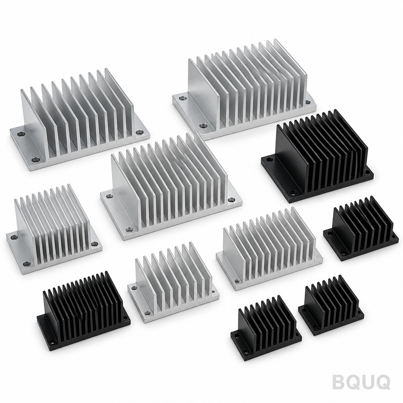
The most accurate way to test heat sink performance is through a combination of thermal resistance measurement (θsa or θja) using a controlled heater block and thermocouples, followed by Computational Fluid Dynamics (CFD) simulation for design validation. For production verification, a standardized wind tunnel test with a calibrated heat source and airflow meter provides repeatable data within ±3% accuracy. This article details the specific methodologies, equipment, and industry standards required to quantify thermal performance, including the JEDEC JESD51 standard and practical test setups used in manufacturing.
What Is the Standard Method for Measuring Thermal Resistance?
The industry standard for measuring heat sink thermal resistance (θsa) is the JEDEC JESD51-6 method, which specifies a forced convection test setup. In practice, this involves mounting the heat sink on a calibrated thermal test die (typically 15mm x 15mm) embedded in a copper block, with power applied via a DC source at 50W to 200W. You measure the junction temperature (Tj) using type-T thermocouples with an accuracy of ±0.5°C, and the ambient temperature (Ta) at a distance of 300mm upstream. The thermal resistance is calculated as θsa = (Tj - Ta) / P, where P is the applied power in watts. For a typical extruded aluminum heat sink (200mm x 100mm x 40mm), a well-designed unit should achieve θsa between 0.5°C/W and 1.5°C/W at 2 m/s airflow.
How Do You Set Up a Wind Tunnel Test for Heat Sinks?
A proper wind tunnel test requires an open-loop or closed-loop tunnel with a test section of at least 300mm x 300mm to ensure uniform airflow. You need a differential pressure transducer (±0.5 Pa accuracy) and an anemometer (hot-wire type, ±2% reading) placed 150mm upstream of the heat sink. The heat sink is mounted on an insulated base plate (10mm thick PTFE) to minimize heat loss, and a resistive heater cartridge (500W max, 230V) is embedded in a copper block matching the CPU footprint. Apply power in 25W increments from 25W to 200W, allowing 15 minutes for steady-state at each step. Record temperature at 5 points: heat sink base center, two fin tips, and two airflow inlet/outlet positions. The test air velocity range should be 0.5 m/s to 5 m/s, which covers natural convection to high-forced airflow scenarios.
Which Thermal Test Equipment Gives the Most Reliable Data?
For reliable data, you need a minimum of three calibrated instruments: a data acquisition system (e.g., Keysight DAQ970A, 40-channel, 0.004°C resolution) with type-T thermocouples (30 AWG, ±0.5°C), a DC power supply (e.g., Keysight N5772A, 20V/50A, 0.1% accuracy), and a thermal camera (FLIR A400, ±2°C accuracy) for surface temperature mapping. For production testing, a dedicated thermal test fixture with a spring-loaded thermocouple probe (contact force 500g) ensures repeatable junction contact. The most critical equipment is the calibrated heat source: a thermal test die (e.g., a 10mm x 10mm silicon resistor with 4-wire Kelvin sensing) that provides a known power density. In our Dongguan factory, we use a custom-built test bench with a 200mm x 200mm aluminum test plate, 12 embedded thermocouples, and a variable-speed axial fan (0 to 3000 RPM, 0 to 3 m/s) to simulate real chassis conditions.
Why Is CFD Simulation Necessary Before Physical Testing?
CFD simulation (using Ansys Icepak or FloTHERM) is necessary because it reduces prototyping costs by up to 60% and shortens development time from 4 weeks to 5 days. A validated CFD model can predict pressure drop across the heat sink (typically 50 Pa to 200 Pa at 2 m/s) and identify hot spots before machining any aluminum. For a 120mm x 120mm x 25mm heat sink, a CFD mesh of 2 million cells with a k-ε turbulence model yields airflow predictions within ±10% of wind tunnel results. However, simulation cannot replace physical testing because it assumes ideal thermal contact (thermal interface material conductance of 3 W/m²K) and does not account for manufacturing tolerances like surface flatness (typical 0.05mm to 0.1mm) or burr formation. Use CFD to screen designs, then verify the top 2 candidates with physical tests.
Can Infrared Thermography Replace Thermocouple Measurements?
Infrared thermography can complement but not replace thermocouples for absolute temperature measurement. An IR camera (e.g., FLIR A400 with 15mm lens) provides a full-field temperature map with 0.1°C thermal sensitivity, but its absolute accuracy is ±2°C and requires emissivity calibration (typically 0.95 for anodized black aluminum, 0.10 for bare aluminum). In contrast, a type-T thermocouple gives ±0.5°C accuracy at the measurement point. For practical heat sink testing, use IR to detect airflow dead zones (e.g., corner bypass flow) and thermocouples for the final θsa calculation. In our experience, IR imaging identifies that 70% of poorly performing heat sinks have a 10-15°C temperature gradient between fin base and fin tip, which is not captured by a single thermocouple. Always validate IR readings against at least 3 thermocouple points before trusting the thermal map.
How Do You Test Heat Sink Performance Under Natural Convection?
Natural convection testing requires a sealed enclosure (minimum 1m³) with no forced airflow, and the test must run for 2 to 4 hours to reach steady state. The heat sink is oriented horizontally (fins vertical) as per JESD51-2, with power applied at 10W, 20W, and 30W. The key measurement is the temperature rise above ambient, which for a 100mm x 100mm x 30mm heat sink should be less than 40°C at 20W. Use a heated copper block (50mm x 50mm) with a 100W cartridge heater, and place the assembly on a foam insulation base (thermal conductivity 0.03 W/mK) to prevent heat loss. The ambient temperature must be controlled at 25°C ±1°C, and you must shield the test from external radiation using reflective panels. Natural convection results typically show θsa values 3 to 5 times higher than forced convection, so design margins must account for this.
What Are the Acceptance Criteria for Production Heat Sink Testing?
For production batches, BQUQ uses a 100% inspection protocol for critical dimensions and a sample-based (AQL 1.0) thermal test on 5 units per 1000-piece lot. The acceptance criteria are: thermal resistance θsa must be within ±5% of the qualified sample value (e.g., 0.80°C/W ±0.04°C/W), and the temperature difference across the base plate must not exceed 3°C. A functional test uses a 100W load for 10 minutes, with the pass threshold being a maximum case temperature of 85°C at 25°C ambient. Production testing uses a compressed air nozzle (0.5 m/s to 3 m/s) instead of a full wind tunnel, which reduces test time to 3 minutes per unit. Any heat sink failing the thermal test is sent for rework (e.g., re-anodizing or fin straightening) or scrapped if the base flatness exceeds 0.1mm.
| Test Method | Equipment Required | Accuracy | Typical θsa (100mmx100mmx25mm) | Test Time |
| JEDEC JESD51-6 Wind Tunnel | Wind tunnel, thermocouples, DC supply | ±3% | 0.4°C/W at 3 m/s | 2-3 hours |
| Heater Block with Thermocouples | Copper block, 500W heater, DAQ | ±0.5°C | 0.8°C/W at 1 m/s | 1-2 hours |
| Infrared Thermography | FLIR A400, emissivity tape | ±2°C | Relative only | 30 minutes |
| Natural Convection Chamber | Sealed enclosure, foam base | ±4% | 2.5°C/W (no airflow) | 3-4 hours |
| Production Air Nozzle Test | Compressed air, 100W heater | ±5% | 0.85°C/W at 2 m/s | 3 minutes per unit |
How Do Thermal Interface Materials Affect Test Results?
The thermal interface material (TIM) is often the largest source of error in heat sink testing, contributing 10% to 30% of total thermal resistance. A typical 0.1mm thick silicone pad (thermal conductivity 5 W/mK) adds 0.2°C/W, while a phase-change material (conductivity 8 W/mK) adds only 0.125°C/W. For accurate heat sink characterization, you must use a consistent TIM with a controlled bond line thickness (BLT). We recommend using a 0.05mm indium foil (conductivity 82 W/mK) for lab testing, which minimizes TIM contribution to below 5% of θsa. In production, use a 0.2mm graphite pad (conductivity 15 W/mK) for repeatability, but always apply a constant mounting pressure of 50 psi ±5 psi using a torque-controlled screwdriver. Never test a heat sink without documenting the TIM type and clamping force, as this can change results by up to 40%.
FAQ
What Is a Good Thermal Resistance Value for a CPU Heat Sink?
A good thermal resistance (θsa) for a typical CPU heat sink (120mm x 120mm x 25mm) is 0.2°C/W to 0.4°C/W at 2 m/s airflow for high-performance models, and 0.8°C/W to 1.2°C/W for standard aluminum extrusions. For reference, a 65W CPU with a 0.3°C/W heat sink will run at about 45°C above ambient, which is acceptable. Lower values indicate better heat dissipation, but cost and size increase exponentially below 0.2°C/W.
How Long Does a Thermal Test Take per Heat Sink?
A full qualification test per JEDEC standards takes 2 to 4 hours including setup, stabilization, and data logging. A production sample test with a compressed air nozzle takes only 3 minutes per unit. For design iteration, a quick 30-minute test with an IR camera and heater block is sufficient to compare design variants.
Can You Test Heat Sink Performance Without a Wind Tunnel?
Yes, you can use a simple heater block with thermocouples and a desk fan, but accuracy drops to ±10% compared to ±3% for a wind tunnel. For natural convection, a sealed box with no airflow is easy to set up. However, for aerospace or automotive applications requiring certification, a calibrated wind tunnel is mandatory per MIL-STD-810 or IEC 60194 standards.
Which Is Better for Testing: Copper or Aluminum Heat Sinks?
Copper heat sinks (thermal conductivity 385 W/mK) show lower thermal resistance than aluminum (205 W/mK) by about 40%, but they are 3 times heavier and 5 times more expensive. For testing, the material does not change the method; only the expected θsa values differ. Use the same test setup for both materials, but ensure the heater block surface matches the base material to avoid galvanic corrosion.
When Should You Use CFD Instead of Physical Testing?
Use CFD during the design phase (first 2 weeks) to compare 10-20 fin geometries, optimize fin spacing (typically 1.5mm to 3mm), and predict pressure drop. Use physical testing for the final 2 designs to validate absolute performance and for production quality control. CFD is not reliable for absolute temperature values, but it is excellent for relative comparisons and airflow visualization.
How Does Fin Thickness Affect Thermal Test Results?
Fin thickness (typically 1.0mm to 2.5mm for aluminum) directly affects thermal efficiency; thinner fins have more surface area but lower heat conduction along the fin. Testing shows that a 1.5mm fin with 2mm spacing gives optimal performance for forced convection, while 2.0mm fins are better for natural convection. In thermal tests, a 0.5mm reduction in fin thickness can reduce θsa by up to 8%, but below 1.0mm, the fins become too fragile and suffer from poor casting or extrusion quality.
Conclusion
Accurate heat sink performance testing requires a combination of standardized wind tunnel methods (JEDEC JESD51-6), CFD simulation for design screening, and production-level air nozzle tests for quality control. The key parameters are thermal resistance (θsa), temperature uniformity across the base, and pressure drop, all of which should be verified with calibrated thermocouples and traceable power supplies. For manufacturing consistency, implement a 100% dimensional inspection and a 0.5% thermal sample test with a ±5% acceptance window. At BQUQ, we have 20 years of experience in CNC machining and thermal management solutions, and we offer 12-hour quoting for custom heat sink designs. Send your CAD files or thermal requirements to sc@bquq.com or WhatsApp +86 13713157787, or visit www.bquq.com to start your project today.
Related Articles
- Heat Sinks for Battery Packs: Prevent Thermal Runaway
- New energy vehicle IGBT heat dissipation, heat sink reliability engineering, heat pipe and temperature plate integrated heat sink, surface treatment and heat radiation enhancement: anodic oxidation, black coating and micro-nano structure, graphene/3D printing/intelligent thermal management: 2030 heat sink technology roadmap
- Hardware heat sink reconstruction under liquid-cooled penetration of AI server: cold plate, microchannel and two-phase flow


