Metal Stamping Tolerances: What to Expect and How to Specify
Metal Stamping Tolerances: What to Expect and How to Specify
In metal stamping, standard tolerances for blanking and piercing range from +/- 0.05 mm to +/- 0.13 mm, while forming and bending tolerances typically fall between +/- 0.10 mm and +/- 0.25 mm. For high-precision applications, advanced progressive die stamping can achieve tolerances as tight as +/- 0.01 mm, but this requires specific material conditions, die construction, and a corresponding increase in cost. Understanding these limits and how to specify them correctly will prevent unnecessary scrap, reduce tooling costs, and ensure your part functions as intended.
The Baseline: Industry Standard Tolerances for Metal Stamping
The precision you can expect from a metal stamping operation depends on the process type. The table below outlines the typical achievable tolerances based on our 20 years of production data at BQUQ (Dongguan, China). These are real-world numbers, not theoretical maximums.
| Process Type | Feature | Standard Tolerance (mm) | Precision Tolerance (mm) | Typical Lead Time (from tooling approval) | :--- | :--- | :--- | :--- | :--- | **Blank & Pierce** | Hole Diameter | +/- 0.10 | +/- 0.025 | 2-3 weeks | **Blank & Pierce** | Outer Profile | +/- 0.13 | +/- 0.05 | 2-3 weeks | **Progressive Die** | Hole-to-Hole Center | +/- 0.05 | +/- 0.015 | 3-4 weeks | **Progressive Die** | Edge-to-Hole (within 5mm) | +/- 0.08 | +/- 0.02 | 3-4 weeks | **Bending (V-Die)** | Bend Angle | +/- 1 degree | +/- 0.5 degree | 1-2 weeks | **Bending (V-Die)** | Bend-to-Hole Position | +/- 0.15 | +/- 0.05 | 1-2 weeks | **Deep Drawing** | Wall Thickness | +/- 0.15 | +/- 0.05 | 4-6 weeks | **Coining** | Surface Flatness (per 100mm) | +/- 0.10 | +/- 0.03 | 2-3 weeks |
|---|
**Key takeaway:** The "Standard" column represents what you should expect with a conventional tool steel die and standard press setup. The "Precision" column requires carbide dies, tighter press alignment, and often secondary processes (grinding or coining).
Section 1: The Three Variables That Destroy Your Tolerance
Before specifying a tolerance, you must understand that a stamped part is not a machined part. Machining removes material; stamping fractures and displaces it. Three physical variables dominate tolerance control:
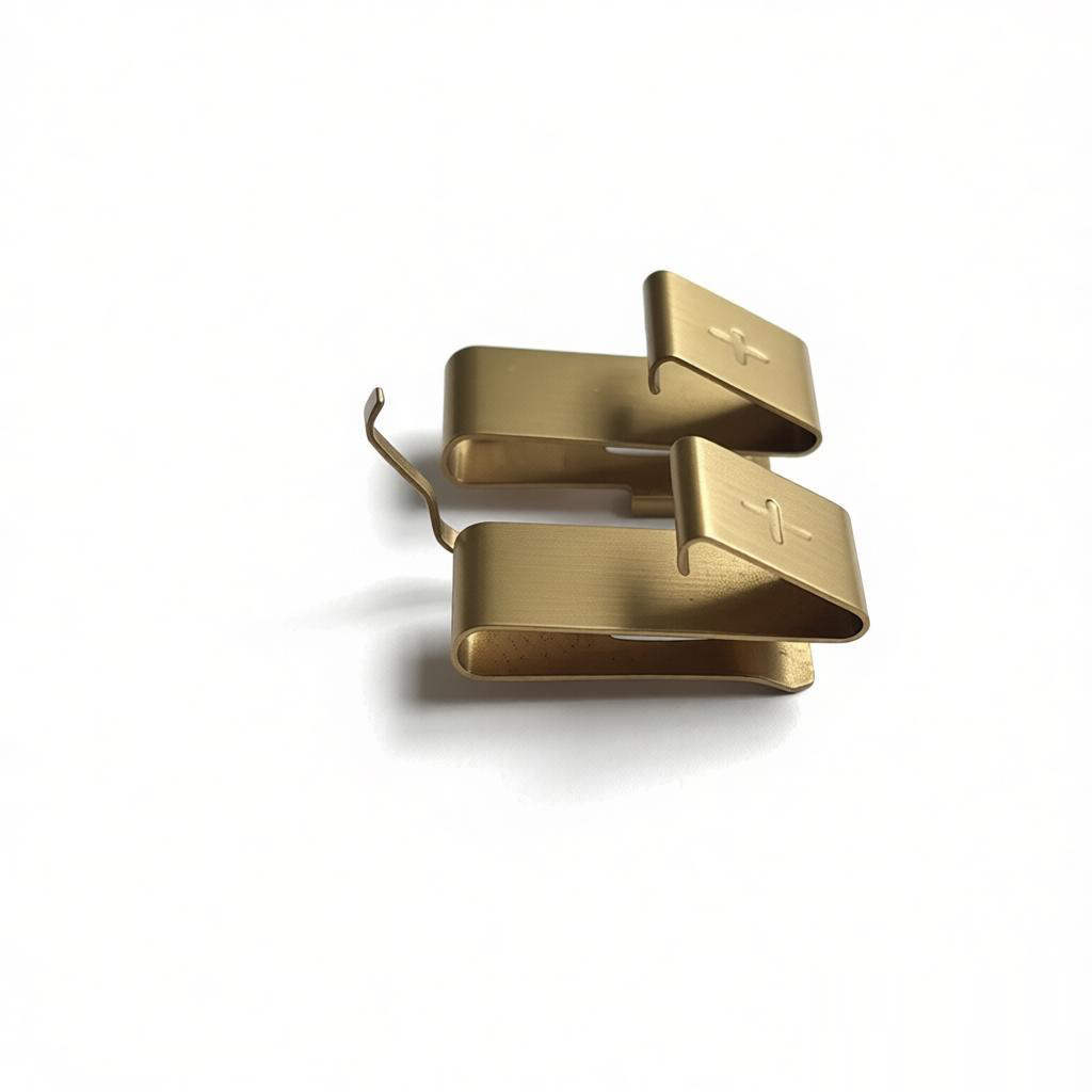
1. **Material Springback:** Steel and aluminum have a modulus of elasticity. When you bend a sheet, it springs back toward its original shape. For a 90-degree bend in 1.0mm thick SPCC steel, expect springback of 2 to 4 degrees. We compensate for this by over-bending the die (springback compensation), but consistency depends on material hardness variation (e.g., HRB 60 vs. HRB 80 changes the result).
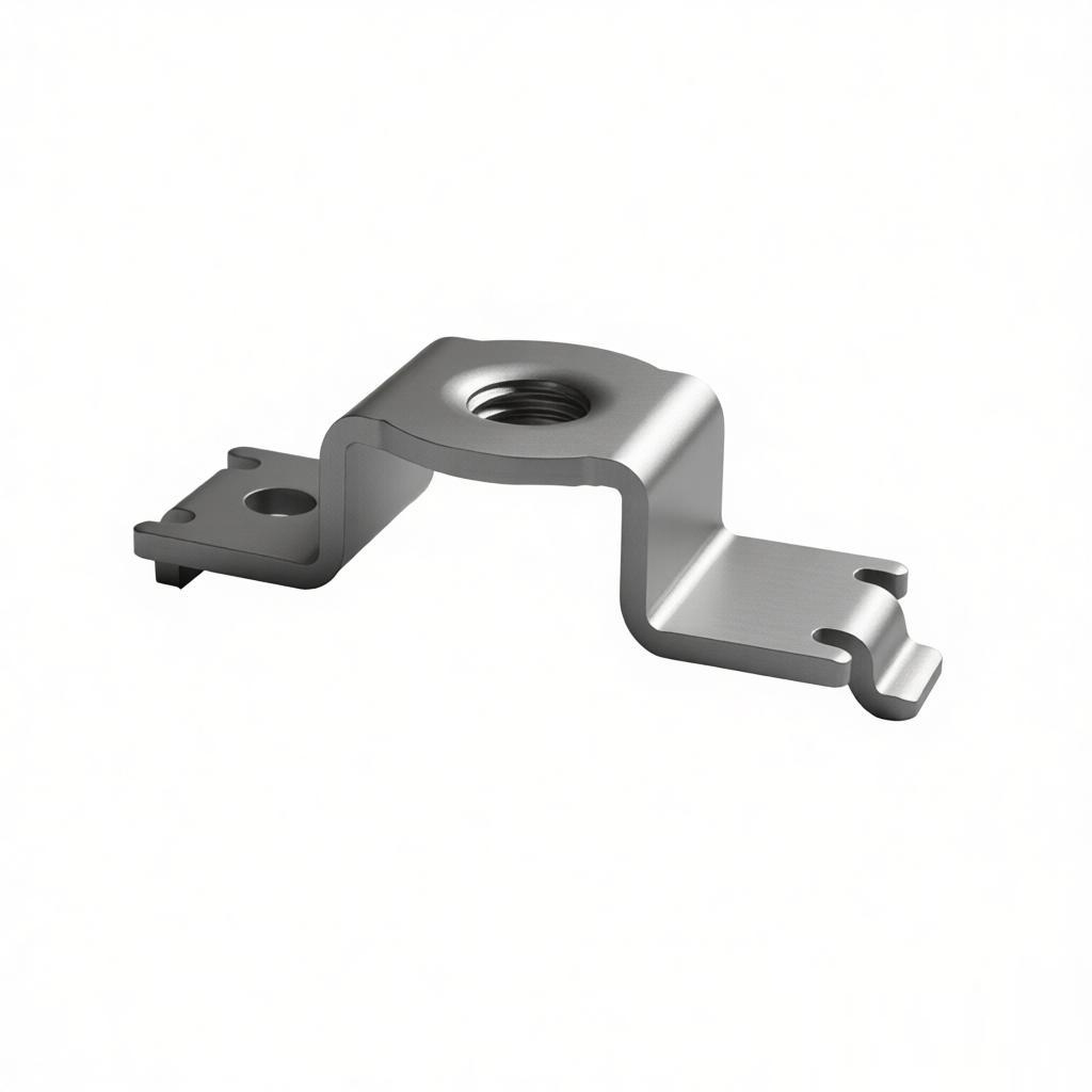
2. **Burr Height:** Punch and die clearance dictates the fracture angle. With optimal clearance (typically 5-10% of material thickness per side), burr height is controlled to 0.05mm or less. If you specify a critical edge tolerance, you must also specify a maximum burr height (e.g., 0.05mm max), otherwise, the sharp edge will violate your profile tolerance.
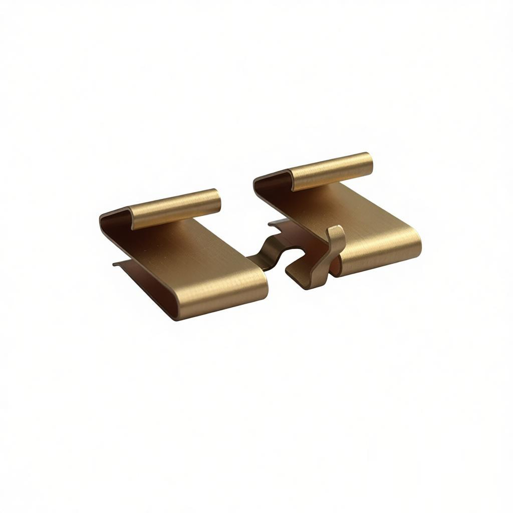
3. **Tool Wear:** A carbide punch will hold a hole diameter of +/- 0.01mm for approximately 500,000 strokes. A standard D2 tool steel punch will begin to wear beyond +/- 0.025mm after only 150,000 strokes. Your tolerance dictates the tool material, which directly impacts the piece part price.
Section 2: How to Specify Tolerances Correctly on Your Drawing
The most common mistake engineers make is applying a blanket tolerance (e.g., "all dimensions +/- 0.05mm") to a stamped part. This is expensive and often impossible. Instead, use the **GD&T (Geometric Dimensioning and Tolerancing)** approach specifically for stampings:
Section 3: The Cost of Tight Tolerances: Real Price Impact
Tight tolerances are not free. At BQUQ, we price this as a "Precision Index." Here is the real cost multiplier based on our 2024 quotation data:
| Tolerance Requirement | Tooling Cost Multiplier (vs. Standard) | Piece Part Cost Multiplier (vs. Standard) | :--- | :--- | :--- | Blanking: +/- 0.13mm (Standard) | 1.0x | 1.0x | Blanking: +/- 0.05mm | 1.3x | 1.15x | Blanking: +/- 0.02mm (Precision) | 1.8x | 1.4x | Forming: +/- 0.25mm (Standard) | 1.0x | 1.0x | Forming: +/- 0.10mm | 1.4x | 1.25x | Forming: +/- 0.05mm (Requires coining step) | 2.0x | 1.8x |
|---|
**Engineering reasoning:** The cost increase is not arbitrary. Moving from +/- 0.13mm to +/- 0.02mm requires switching from a stamped die plate to a wire-cut carbide insert. It also requires a high-precision press (C-frame vs. straight-side) with a bed parallelism of less than 0.01mm, and it increases inspection time from a caliper check to a CMM (Coordinate Measuring Machine) check.
Section 4: Practical Recommendations for Critical Features
If you have a feature that truly requires high precision, follow these rules to keep your project on budget and on schedule:
1. **Rule of 10 for Material Thickness:** Do not specify a hole size tolerance tighter than 10% of the material thickness. For 1.0mm steel, the minimum practical hole diameter is 1.0mm (equal to thickness). A tolerance of +/- 0.01mm on a 1.0mm hole is a breaking rule; it requires a special punch guide and will yield high punch breakage.
2. **Use Secondary Operations for True Precision:** If you need a hole diameter of +/- 0.005mm, do not attempt to stamp it. Pierce the hole undersized (e.g., 1.90mm) and then perform a **piercing-and-burnishing** operation or a reaming operation. This adds a secondary process (approximately $0.02-$0.05 per part) but is far more reliable than trying to hold a stamping die to that limit.
3. **Specify Flatness for Stress Relief:** When you stamp a part from a coil, internal stresses are locked in. If you require flatness better than 0.10mm over 100mm, you must specify "stress relief" or "leveling" as a process step. This involves passing the part through a roller leveler or a heat treatment at 350-400 degrees Fahrenheit (175-200 degrees Celsius) for 1-2 hours. Without this specification, parts will warp after you cut the strip.
Section 5: FAQ-Style Tips for Your Next RFQ
**Q: Can you hold +/- 0.01mm on a stamped part?** A: Yes, but only on small features (less than 10mm) in material under 2.0mm thick, and only with a carbide die. It is not a "standard" process. Expect a 2.0x tooling cost and a 1.5x piece price premium. For 99% of applications, +/- 0.05mm is sufficient.
**Q: Should I use ISO 2768-mK or a specific drawing callout?** A: ISO 2768-mK gives a general tolerance of +/- 0.1mm for dimensions up to 30mm, which is fine for rough work. However, for stamped parts, we recommend you ditch the general tolerance and explicitly call out critical dimensions on the drawing (e.g., "Hole A: 5.00 +/- 0.03" and "True Position of Hole A relative to A/B/C datums: 0.10"). This eliminates ambiguity for the toolmaker.
**Q: How does material thickness affect my tolerance?** A: The rule of thumb is that tolerance tightens with thinner material. For 0.5mm phosphor bronze, you can hold +/- 0.02mm on hole centers. For 5.0mm thick aluminum, the tolerance loosens to +/- 0.15mm because the punch deflects and the material tears, not shears.
**Q: What is the minimum bend radius for a tight tolerance?** A: For a sharp bend (inside radius less than 0.5x material thickness), the tolerance on the angle becomes unstable. We recommend an inside bend radius of 1.0x to 1.5x material thickness to maintain a stable angle tolerance of +/- 0.5 degrees. A sharper radius increases the risk of cracking and inconsistent springback.
Conclusion: Get the Tolerance Right the First Time
Metal stamping is a high-volume, cost-effective process, but its success hinges on realistic tolerance specification. Remember the baseline: +/- 0.05mm to +/- 0.13mm for cutting, and +/- 0.10mm to +/- 0.25mm for forming is your cost-effective sweet spot. Push to the precision limits only when the function absolutely requires it, and always communicate the critical features, not the entire drawing. By doing so, you will reduce tooling costs by up to 40% and cut your lead time by weeks.
If you are currently reviewing a drawing or are unsure whether your tolerance is achievable, send us your file. We will provide a detailed DFM (Design for Manufacturing) report within 12 hours, including a tolerance analysis and a firm quote.
**Get your free tolerance and cost analysis today.** - Email: sc@bquq.com - WhatsApp: +86 13713157787 - Website: www.bquq.com
Our engineering team in Dongguan has 20 years of experience in CNC machining and metal stamping, and we are ready to help you manufacture with confidence.
Related Articles
- Stamping Press Selection Guide 2024: Mechanical vs Hydraulic vs Servo Speed and Force
- Why Low Volume Metal Stamping is Ideal for Prototyping
- Stamping Lubricant Selection 2024: Balancing Die Life, Part Quality, and Environmental Compliance
Frequently Asked Questions
What are the standard tolerances for metal stamping blanking and piercing?
Standard tolerances for blanking and piercing range from +/- 0.05 mm to +/- 0.13 mm. Specifically, hole diameter is typically +/- 0.10 mm, and outer profile is +/- 0.13 mm. Precision tolerances can reach +/- 0.025 mm for holes and +/- 0.05 mm for profiles with carbide dies and secondary processes.
Can you achieve tighter tolerances than the standard, and what does it require?
Yes, high-precision progressive die stamping can achieve tolerances as tight as +/- 0.01 mm, but this requires specific material conditions, carbide die construction, tighter press alignment, and often secondary processes like grinding or coining. This increases cost and lead time compared to standard tool steel dies.
How much springback should I expect when bending 1.0mm thick SPCC steel?
For a 90-degree bend in 1.0mm thick SPCC steel, expect springback of 2 to 4 degrees. We compensate by over-bending the die, but consistency depends on material hardness variation, such as HRB 60 versus HRB 80, which changes the result.
What is the typical burr height control in metal stamping?
With optimal punch and die clearance, typically 5-10% of material thickness per side, burr height is controlled to 0.05mm or less. If you specify a critical edge tolerance, you must also specify a maximum burr height, such as 0.05mm max, to avoid profile tolerance violations.