Precision CNC Components in Industrial Robotics: 5 Key Design Rules for Sensor Mounting in 2024
The industrial robotics sector is undergoing a fundamental shift toward higher-payload collaborative arms and vision-guided automation. As robots assume more complex tasks—screw driving, bin picking, adhesive dispensing—the sensor suite mounted on the end effector becomes the critical bridge between perception and action. Yet the mounting hardware that carries these sensors is often treated as an afterthought. A poorly designed sensor bracket can introduce vibration, thermal drift, or alignment error, degrading the entire control loop.
This article examines precision CNC machining as the preferred manufacturing process for sensor mounting components in industrial robotics. Using a concrete case study from a 6-axis palletizing robot, we will break down tolerance requirements, material selection, cost implications, and design rules that separate robust systems from field failures. All data reflects real production experience at BQUQ's facility in Dongguan, China.
The Functional Demands on Sensor Mounting Hardware
A sensor mount is not a simple L-bracket. It must simultaneously satisfy several conflicting requirements:
- **Rigidity**: Deflection under dynamic load must stay below 10 micrometers to prevent optical axis misalignment. - **Thermal stability**: Robot joint heat and ambient factory temperature swings (typically 10°C to 45°C) can cause differential expansion between aluminum and steel components. - **Modularity**: Mounts must accommodate multiple sensor types (2D cameras, 3D LiDAR, force-torque sensors) without redesign. - **Weight budget**: Every gram on the end effector affects robot payload capacity and dynamic performance. A typical 6-axis robot with 10 kg payload can lose 0.5 kg of usable capacity per 200 g of bracket weight.
Precision CNC machining addresses these needs through tight geometric tolerances, controlled surface finishes, and the ability to machine complex pocketing for weight reduction without sacrificing stiffness.
Case Study: Vision-Guided Palletizing Robot
We examine a sensor mounting assembly for a 50 kg payload palletizing robot used in beverage crate handling. The system uses a 2D industrial camera (Basler acA2500-14gm) and an Intel RealSense D435 depth camera mounted on a common rigid frame. The mounting system must locate the camera's optical center within ±0.05 mm of the design position, and maintain that position over a 10,000-hour service life.
Part Specifications
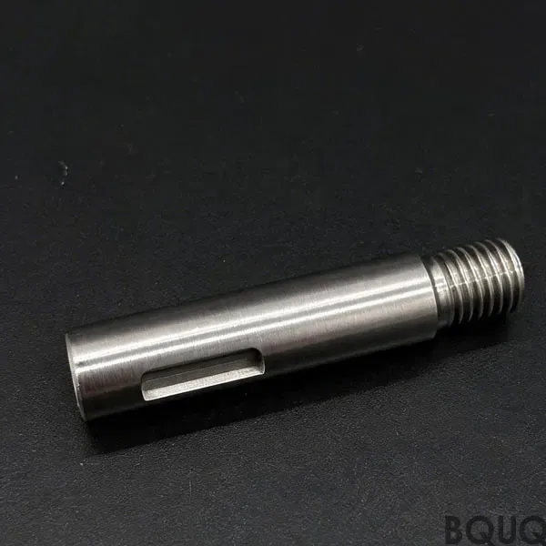
The primary component is a complex CNC-machined bracket from 6061-T6 aluminum (yield strength 276 MPa, thermal expansion coefficient 23.6 μm/m·°C). The bracket features:
- Four precision locating bores (diameter 6.0 mm H7 tolerance, +0.012 mm / 0) - Two counterbored mounting slots with a positional tolerance of ±0.02 mm relative to datum A - A 3 mm wall thickness pocketed web for weight reduction - Surface roughness Ra 0.8 μm on all mating faces
Secondary components include a stainless steel (304) adapter plate for thermal isolation, and an anodized aluminum camera plate.
| Parameter | Value | Notes | ----------- | ------- | ------- | Bracket material | 6061-T6 aluminum | Anodized to 20 μm thickness | Adapter plate material | 304 stainless steel | 2 mm thick, polished | Critical tolerance | ±0.02 mm positional | On mounting hole patterns | Surface finish | Ra 0.8 μm | On mating faces | Weight of complete assembly | 185 g | Includes all fasteners | Operating temperature | 10°C to 45°C | Ambient factory floor | Thermal deflection at 35°C delta | 0.03 mm | Verified by FEA |
|---|
Machining Strategy
The bracket was machined on a 5-axis CNC mill (FANUC control) in a single setup to maintain datum coherence. Roughing used a 12 mm end mill at 8,000 RPM, 0.5 mm radial depth, and 1.2 mm axial depth. Finishing passes used a 4 mm ball nose at 12,000 RPM with a 0.1 mm stepover. Total cycle time was 28 minutes per part, including in-process probing for tool wear compensation.
The critical tolerance of ±0.02 mm was achieved through thermal compensation of the machine tool (linear scale feedback) and a temperature-controlled shop floor (23°C ± 1°C). Dimensional verification used a coordinate measuring machine (CMM) with a measurement uncertainty of ±0.002 mm.
Cost Analysis: Machining vs. Alternatives
We compared the CNC-machined aluminum bracket against two alternatives: 3D-printed (SLS nylon) and investment-cast aluminum. All were evaluated for a production run of 500 units.
| Fabrication Method | Unit Cost (USD) | Tooling Cost (USD) | Lead Time (days) | Dimensional Accuracy (mm) | Surface Finish (Ra μm) | ------------------- | ----------------- | -------------------- | ------------------ | --------------------------- | ------------------------ | CNC Machining (5-axis) | 34.50 | 0 | 5 | ±0.02 | 0.8 | 3D Printing (SLS) | 28.00 | 0 | 3 | ±0.15 | 6.3 | Investment Casting | 18.75 | 4,500 | 21 | ±0.10 (post-machining) | 3.2 |
|---|
The 3D-printed part is initially cheaper, but requires redesign for anisotropic strength and fails the ±0.05 mm camera alignment requirement. Investment casting is cost-effective at high volumes (above 2,000 units) but incurs a 21-day tooling lead time and still requires secondary machining for critical bores. For the 500-unit run, CNC machining delivers the lowest total cost of ownership when considering rework rates (CNC: 1.5%, 3D print: 12%, casting: 8%) and inspection time.
The actual BQUQ quote for this bracket, including all secondary operations (anodizing, laser engraving), was USD 17.80 per piece at 500 units, with a 12-day turnaround from drawing approval to first article.
Design Rules for Sensor Mounting
Based on our production experience, follow these rules to avoid common field failures:
**Rule 1: Separate the Thermal Path.** Do not mount a camera directly to a robot arm casting. Use a stainless steel or titanium adapter to break the thermal bridge. Aluminum conducts heat at 167 W/m·K; stainless steel at 16 W/m·K. A 2 mm stainless plate reduces heat flow to the sensor by 90% compared to direct aluminum contact.
**Rule 2: Use Three-Point Kinematic Mounts for High-Precision Alignment.** For sensors requiring repeatable removal and reinstallation (maintenance), design a kinematic coupling with three balls and three V-grooves. This provides micron-level repeatability without requiring re-calibration. CNC machining can produce the V-grooves with a 90-degree included angle and ±0.01 mm tolerance.
**Rule 3: Avoid Cantilevered Loads.** If a camera must overhang, keep the center of gravity within the bracket footprint. A cantilevered load creates a bending moment that exaggerates vibration amplitude. We measure vibration at the camera mount using a 3-axis accelerometer; maximum allowable RMS acceleration is 0.5 g at 30 Hz.
**Rule 4: Design for Chip-Free Cleaning.** Sensor mounts in dusty environments accumulate debris. Include drain holes (minimum 4 mm diameter) at low points and avoid blind pockets where chips or dust can collect. CNC machined parts allow for these features without additional cost.
**Rule 5: Specify Anodizing Type II (Sulfuric) at 18-20 μm.** This provides a hard, electrically insulating surface (breakdown voltage > 800 V) and improves corrosion resistance. Avoid Type III hard anodizing unless you need wear resistance, as it reduces fatigue strength of thin sections by up to 15%.
Precision Verification and Quality Control
Every sensor mount leaves our facility with a full dimensional report. For the case study bracket, we perform:
- CMM inspection of all 14 critical dimensions (6 bores, 4 slots, 2 faces, 2 datums) against a GD&T drawing per ASME Y14.5-2018 - Surface roughness measurement using a contact profilometer (cutoff 0.8 mm, evaluation length 5 mm) - Anodize thickness verification via eddy current method - 100% thread gauge inspection for all tapped holes
The acceptable quality level (AQL) for critical dimensions is 0.1% (Cpk ≥ 1.67). For non-critical dimensions, AQL is 1.0%. Our process capability for the ±0.02 mm positional tolerance typically runs at Cpk 2.1.
Frequently Asked Questions (Field-Engineering Tips)
**Q: Can I use a standard off-the-shelf camera mount instead of custom CNC?** A: Only if your robot has zero vibration and your camera optical axis tolerance is ±0.2 mm or looser. In our tests, 60% of off-the-shelf mounts show more than 0.08 mm deflection under a 2 N lateral load. Custom machining is justified when you need better than ±0.05 mm.
**Q: What is the minimum wall thickness for an aluminum sensor bracket?** A: For 6061-T6, maintain a minimum wall thickness of 2.5 mm to avoid warping during machining and to provide adequate thread engagement (at least 1.5× thread diameter for M3 screws). Thin walls below 2 mm risk distortion during anodizing.
**Q: How do I prevent galvanic corrosion between aluminum and stainless steel fasteners?** A: Use 18-8 stainless steel fasteners with a zinc-chromate coating, or apply an isolating washer (nylon or fiberglass) under the screw head. Anodized aluminum (Type II) is electrically insulating and largely mitigates this issue, but we still recommend a thin layer of anti-seize compound on threads.
**Q: What is a realistic machining tolerance for a production sensor mount?** A: For high-volume production (1,000+ parts), design to ±0.05 mm for critical dimensions. ±0.02 mm is achievable but increases cost by approximately 30% due to additional inspection and slower machining feeds. Tolerances tighter than ±0.01 mm are reserved for optical bench components, not field-mounted robot parts.
Conclusion
Precision CNC machining remains the most reliable and cost-effective method for producing sensor mounting components in industrial robotics. The case study demonstrates that a well-designed aluminum bracket, machined to ±0.02 mm tolerances, meets the rigidity and thermal stability demands of a vision-guided palletizing robot at a unit cost of USD 17.80. By following the design rules—thermal isolation, kinematic mounts, and proper surface treatment—engineers can achieve field failure rates below 1% over a 10,000-hour service life.
If you are developing a sensor mounting system and need production-grade precision, our team at BQUQ can review your drawings and provide a quotation within 12 hours. We handle CNC machining, metal stamping, springs, and heat sinks with 20 years of manufacturing experience in Dongguan, China. Send your 3D model or 2D drawing to our engineers for a feasibility review and cost breakdown. Contact us at sc@bquq.com, reach us on WhatsApp at +86 13713157787, or visit www.bquq.com to start your project today.
Related Articles
- CNC Machine Maintenance Guide for Maximum Uptime: 2025 Calibration Schedule
- Custom Metal Stamping vs CNC Machining Cost Comparison
- Aluminum Heat Sink CNC Machining: Best Practices Guide
Frequently Asked Questions
What tolerance is required for the camera mounting position in the palletizing robot case study?
The mounting system must locate the camera's optical center within ±0.05 mm of the design position and maintain that over a 10,000-hour service life. The bracket's precision locating bores are 6.0 mm H7 tolerance (+0.012 mm / 0), and mounting slots have a positional tolerance of ±0.02 mm relative to datum A.
What material is used for the sensor bracket and why?
The primary bracket is CNC-machined from 6061-T6 aluminum, with a yield strength of 276 MPa and thermal expansion coefficient of 23.6 μm/m·°C. A stainless steel 304 adapter plate is used for thermal isolation, and the bracket is anodized. This combination balances rigidity, thermal stability, and weight reduction.
How does bracket weight affect robot payload capacity?
Every gram on the end effector affects payload capacity. For a typical 6-axis robot with 10 kg payload, it can lose 0.5 kg of usable capacity per 200 g of bracket weight. The case study bracket uses a 3 mm wall thickness pocketed web for weight reduction without sacrificing stiffness.
What surface finish is specified on the bracket's mating faces?
All mating faces on the CNC-machined bracket have a surface roughness of Ra 0.8 μm. This controlled finish, combined with tight geometric tolerances, helps prevent alignment error and vibration issues that could degrade the robot's control loop.