Progressive Die Design Principles for Metal Stamping: Key Rules and Data
Progressive Die Design Principles for Metal Stamping: Key Rules and Data
**The direct answer:** Progressive die design is governed by strip layout optimization, station balance, and precision alignment, with standard tolerances held to ±0.025 mm for critical features and ±0.05 mm for general dimensions. A well-designed progressive die for 0.5–3.0 mm sheet steel typically runs at 200–600 strokes per minute, producing 90–95% material utilization, and costs between $15,000 and $80,000 depending on part complexity and die size.
---
1. Strip Layout: The Foundation of Progressive Die Efficiency
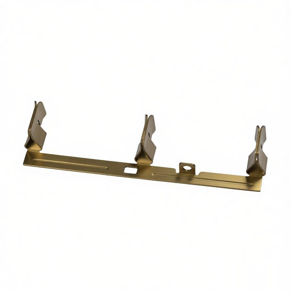
Strip layout is the single most influential decision in progressive die design. It determines material utilization, number of stations, and defect rates. For a typical 2.0 mm thick SPCC steel part, the pilot hole should be designed at least 1.5 times the material thickness from the strip edge. Minimum web width between adjacent cutouts is 1.2× material thickness for blanking, but must be increased to 1.5× if the die runs above 300 SPM to prevent slug pulling.
Material utilization targets vary by part geometry: - Simple flat blanks: 85–92% - Parts with bends and forms: 75–85% - Deep-drawn or complex multi-plane parts: 60–75%
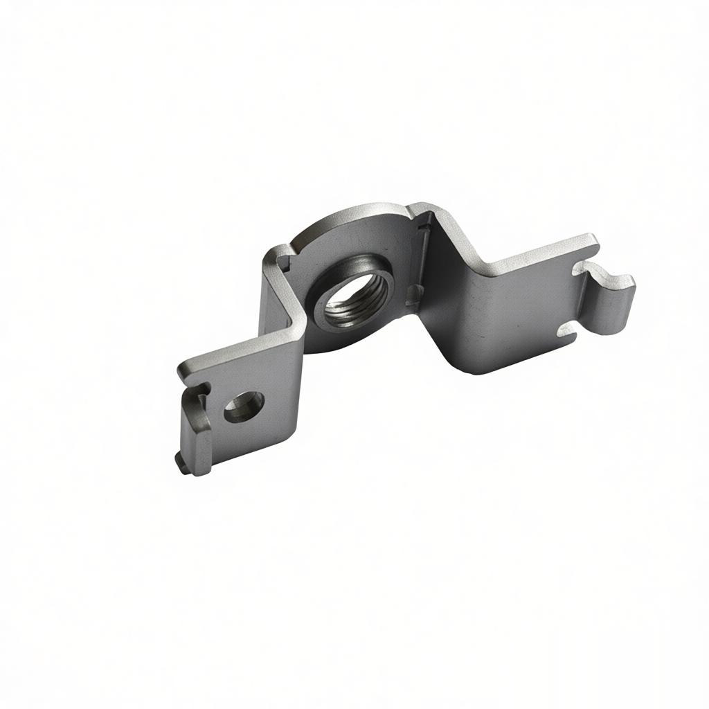
Our BQUQ engineering team consistently achieves 90%+ utilization on flat parts by nesting parts at optimal angles (typically 30–45 degrees) and using a carrier strip width that accommodates both pilot holes and part geometry without excess scrap. For example, a rectangular bracket 50 mm × 30 mm in 1.5 mm thick galvanized steel uses a 55 mm strip with 2.5 mm pitch progression, yielding 92% material efficiency.
---
2. Station Balancing and Tonnage Calculation
Each station in a progressive die must be balanced to prevent uneven wear and premature tool failure. The rule of thumb: no single station should exceed 30% of the total press tonnage. For a 25-ton press running a 10-station die, each station should draw no more than 7.5 tons.
Tonnage calculation for blanking: - Shear strength of SPCC (cold-rolled steel): 280–320 MPa - Cutting force (F) = Perimeter (mm) × Thickness (mm) × Shear Strength (MPa) / 1000 (in kN)
Example: A 40 mm diameter hole in 2.0 mm SPCC: - Perimeter = 125.7 mm - F = 125.7 × 2.0 × 300 / 1000 = 75.4 kN (7.7 tons)
Add 20–30% safety margin for stripping force (typically 10–15% of cutting force) and die cushion pressure. For forming stations, tonnage is 2–3× higher than blanking for the same area due to compressive stresses. Always verify press capacity with the peak combined tonnage of simultaneous stations, not the sum of all stations.
---
3. Precision Tolerances and Clearance Specifications
Progressive die clearances directly impact part edge quality and die life. For 2.0 mm thick mild steel, recommended die-to-punch clearance is 5–7% of material thickness per side, meaning 0.10–0.14 mm per side. For stainless steel (SUS304), increase to 8–10% per side. For aluminum (5052), reduce to 3–4% per side.
Typical achievable tolerances in a well-maintained progressive die: - Hole-to-hole position: ±0.025 mm - Hole-to-edge: ±0.05 mm - Bend angle: ±0.5 degrees - Flatness: 0.1 mm per 100 mm length - Formed height: ±0.05 mm
Die component tolerances are tighter. Punches and die buttons are ground to ±0.005 mm, with guide posts holding alignment of ±0.002 mm total runout. High-speed dies require precision ball-bearing guide bushings with preload of 0.01–0.02 mm to eliminate clearance variation at 600 SPM.
| Material | Thickness (mm) | Per-side Clearance (%) | Min. Hole Diameter (× thickness) | Max. SPM (typical) | Die Life (hits) | ---------- | ---------------- | ------------------------ | ---------------------------------- | ------------------- | ----------------- | SPCC | 0.5–1.0 | 4–5% | 1.0× | 600 | 2,000,000 | SPCC | 1.0–2.5 | 5–7% | 1.2× | 400 | 1,500,000 | SPCC | 2.5–4.0 | 7–9% | 1.5× | 250 | 800,000 | SUS304 | 0.5–2.0 | 8–10% | 1.3× | 300 | 1,000,000 | 5052 Al | 0.5–2.0 | 3–4% | 0.8× | 500 | 1,200,000 | Brass C2680 | 0.5–1.5 | 4–6% | 0.9× | 450 | 1,800,000 |
|---|
---
4. Pilot and Carrier System Design
Pilot holes are the referencing system for all subsequent stations. Use at least two pilots per strip, positioned diagonally to provide rotational control. Pilot hole diameter should be 1.6–2.5 mm for thin gauges (under 1.0 mm) and 3.0–5.0 mm for thicker materials. The pilot punch enters the strip with a clearance of 0.01–0.02 mm on diameter, ensuring precise positional repeatability.
Carrier design varies by part: - **Side carrier:** For flat parts, strip edge width of 3–5 mm, with pilot holes in the carrier. Recommended when part has no natural carrier location. - **Center carrier:** For parts requiring bending on both sides, carrier width of 6–10 mm, with pilots on the centerline. Used for U-shaped brackets and clips. - **Double carrier:** For long, narrow parts (length > 10× width), two parallel carriers on both edges, ensuring strip rigidity during high-speed progression.
Pilot misalignment is the leading cause of die crash. Implement pilot protection: if a pilot encounters an obstruction greater than 5–8 N force, the press stops via a sensor within 20 milliseconds, preventing catastrophic damage. At BQUQ, we add optical sensors at every 3rd station in dies running above 300 SPM.
---
5. Temperature Management and Lubrication
Progressive die operation generates significant heat. At 400 SPM with 2.0 mm SPCC, the die zone temperature can reach 60–80°C during continuous production. Above 100°C, punch hardness (typically HRC 60–62 for D2 tool steel) begins to soften, reducing die life by up to 40%.
Lubrication strategy: - Light stamping oil (viscosity 10–20 cSt at 40°C): For materials under 1.5 mm, use spray application at 5–10 ml/min per station. - Medium oil (30–50 cSt): For 1.5–3.0 mm steel, flood application at 15–25 ml/min. - Dry film lubricant: For aluminum and stainless, reduces galling, applied via roller coater.
Cooling for high-speed dies: use internal coolant channels in the die base (water circulation at 5–10 L/min) when SPM exceeds 500. This maintains die temperature within ±5°C, ensuring consistent thermal expansion of tool steel (11.5 × 10⁻⁶ /°C for D2). A 200 mm long die block expands 0.023 mm per 10°C change, which exceeds tolerance limits if uncontrolled.
---
6. Cost Optimization and Die Life Economics
Progressive die cost scales with station count and part complexity. A simple 4-station die for a flat washer costs $8,000–$12,000. A medium 10-station die for a bracket with bends costs $25,000–$40,000. A complex 20-station die with deep draws and cam units costs $60,000–$80,000.
Die life economics: - Standard D2 tool steel punches: 1–2 million hits before regrind (0.1–0.2 mm stock removal) - Tungsten carbide inserts (for high-volume aluminum): 5–10 million hits, 3× cost of D2 but 5× life - Powder metallurgy steel (PM23): 2–4 million hits, good for stainless steel
Maintenance interval: preventive regrind every 500,000 hits for D2, every 1,000,000 for carbide. Each regrind cycle costs $300–$500 and takes 8–16 hours of downtime. Total die cost per part: divide (die cost + maintenance cost) by total parts produced. For a 10-station die producing 2,000,000 parts over 3 years, cost per part is $0.02–$0.04, excluding material and press time.
---
Practical Recommendations for Engineers
1. **Design for manufacturability first:** Avoid tight tolerances on non-critical features. A hole tolerance of ±0.05 mm costs 20% less in tooling than ±0.025 mm. Only critical mounting holes require the tighter spec. 2. **Use finite element analysis (FEA) for bending:** Springback in 2.0 mm SPCC with 90° bend is 1–3 degrees. Compensate by over-bending 2 degrees in the die design, confirmed with FEA before tool steel cutting. 3. **Plan for slug control:** Use slug retainers or suction systems in blanking stations. Loose slugs cause 60% of progressive die jams. Install slug sensors at every blanking station. 4. **Consider progressive vs. compound vs. transfer:** For parts under 50 mm, with simple bends, progressive is fastest. For deep draws (depth > 2× diameter), transfer dies are more reliable. For very high volume simple parts, compound dies with 2–3 hits are cheaper.
---
FAQ-Style Design Tips
**Q: What is the minimum pilot hole size for 0.8 mm thick steel?** A: Minimum 1.2 mm diameter, but we recommend 1.6 mm for reliability. Smaller pilots break at high speed due to bending stress.
**Q: How many stations should a typical progressive die have?** A: For a part with 1 bend and 3 holes: 5–7 stations. For complex parts with 3 bends, a lance, and a form: 12–15 stations. Never design fewer than 2 stations per bend if the bend is over 90 degrees.
**Q: What is the maximum strip width for a standard progressive die?** A: For presses up to 60 tons, strip widths of 50–200 mm are standard. Above 200 mm, die cost increases exponentially due to larger plates and alignment challenges.
**Q: How do I prevent edge burr in progressive stamping?** A: Maintain punch-to-die clearance within spec (5–7% per side for steel). Burr height should be under 0.05 mm. If burr exceeds 0.1 mm, regrind punches immediately. Also check for punch wear at every 100,000 hits.
---
Conclusion
Progressive die design is a balance of geometry, material science, and mechanical precision. The key numbers to remember: ±0.025 mm critical tolerance, 5–7% per-side clearance for steel, 300–600 SPM operating speed, and 1.5–2.0 million hits per regrind cycle. Following these design principles reduces scrap, extends die life, and cuts per-part cost by 15–30% compared to ad-hoc designs. A properly designed progressive die pays for itself within 6–12 months at production volumes above 500,000 parts per year.
At BQUQ, we have 20 years of progressive die design and manufacturing experience in Dongguan, China. Our engineering team provides die design validation, FEA analysis, and full production support. We respond to all quoting requests within 12 hours. Contact us at sc@bquq.com, WhatsApp +86 13713157787, or visit www.bquq.com with your part drawings for an immediate feasibility assessment and cost estimate.
Related Articles
- Stamping Press Selection Guide 2024: Mechanical vs Hydraulic vs Servo Speed and Force
- Stamping Lubricant Selection 2024: Balancing Die Life, Part Quality, and Environmental Compliance
- How Metal Stamping Improves Heat Sink Efficiency
Frequently Asked Questions
What tolerances can I expect from a progressive die metal stamping process?
Standard progressive die tolerances are ±0.025 mm for critical features and ±0.05 mm for general dimensions. For a 2.0 mm thick mild steel part, recommended die-to-punch clearance is 5–7% of material thickness per side (0.10–0.14 mm). Stainless steel requires 8–10% per side, while aluminum 5052 uses 3–4% per side.
How much does a progressive die cost and what production speed can I expect?
A well-designed progressive die for 0.5–3.0 mm sheet steel typically costs between $15,000 and $80,000, depending on part complexity and die size. Production speeds range from 200 to 600 strokes per minute, with material utilization of 90–95% on flat parts. Our team achieves 90%+ utilization on flat parts through optimal nesting.
What material utilization rates can I achieve for different part geometries?
Material utilization targets vary by geometry: simple flat blanks achieve 85–92%, parts with bends and forms reach 75–85%, and deep-drawn or complex multi-plane parts run 60–75%. For example, a 50 mm × 30 mm rectangular bracket in 1.5 mm galvanized steel uses a 55 mm strip with 2.5 mm pitch, yielding 92% efficiency.
How do you calculate tonnage requirements for progressive die stations?
No single station should exceed 30% of total press tonnage. For blanking, cutting force (kN) = Perimeter (mm) × Thickness (mm) × Shear Strength (MPa) / 1000. A 40 mm hole in 2.0 mm SPCC requires 75.4 kN (7.7 tons). Add 20–30% safety margin for stripping force and die cushion pressure.