
Spring Rate Calculation Guide for CNC Machined and Stamped Springs
What Is Spring Rate and How Do You Calculate It?
Spring rate, expressed in newtons per millimeter (N/mm) or pounds per inch (lbf/in), is the measure of stiffness that defines how much force is required to compress or extend a spring by a unit distance. The calculation is straightforward: divide the applied force by the resulting deflection (k = F/d). For a helical compression spring, the precise formula incorporates material shear modulus, wire diameter, coil diameter, and number of active coils, which we detail below with engineering-grade accuracy.
Understanding Spring Rate Fundamentals
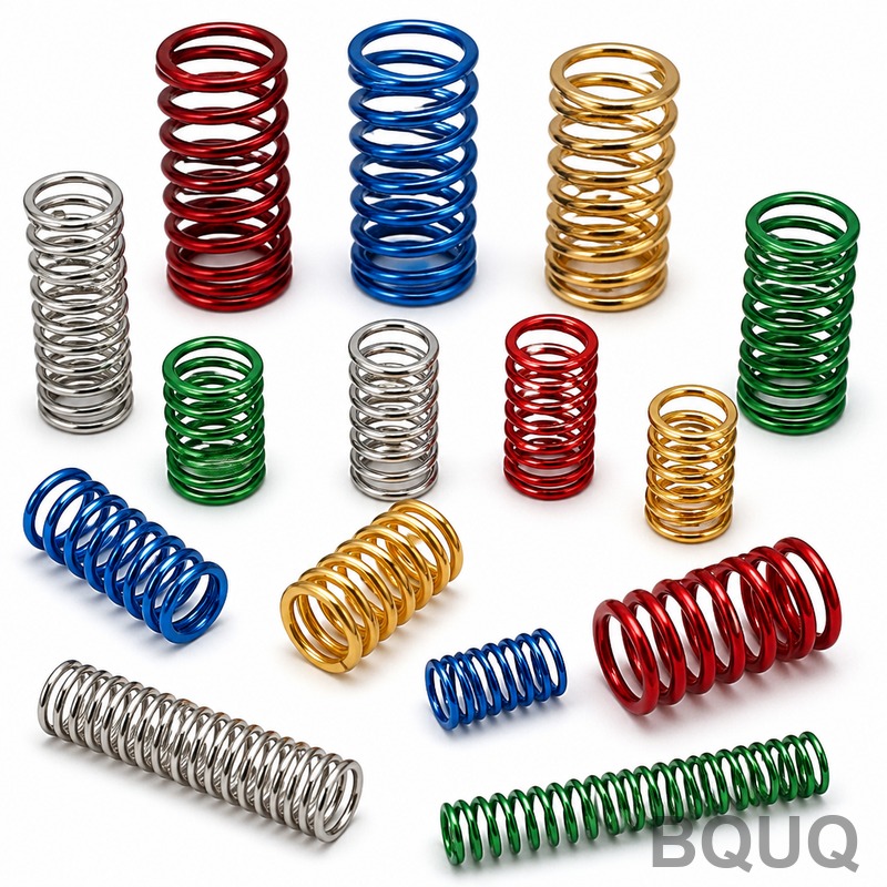
Spring rate is the constant that describes the linear relationship between load and deflection in the elastic region of a spring's travel. For a typical compression spring made of ASTM A228 music wire, the rate remains constant until the spring approaches solid height, at which point the rate increases non-linearly. This characteristic is critical for applications ranging from automotive valve springs to precision medical device mechanisms.
The basic formula for any spring system is: k = F / d Where k is spring rate (N/mm), F is applied force (N), and d is deflection (mm).
For helical compression springs, the full engineering equation is: k = (G x d^4) / (8 x D^3 x Na) Where G is shear modulus (79.3 GPa for spring steel), d is wire diameter (mm), D is mean coil diameter (mm), and Na is number of active coils.
Material Properties That Affect Spring Rate
The shear modulus (G) is the material property that most directly influences spring rate. This value changes with temperature and material grade. For BQUQ's production environment in Dongguan, we commonly process the following materials:
| Material Grade | Shear Modulus (GPa) | Max Operating Temp (°C) | Typical Wire Diameter (mm) | Relative Cost Factor |
| ASTM A228 Music Wire | 79.3 | 120 | 0.1 - 6.0 | 1.0 |
| ASTM A313 302 Stainless | 77.2 | 250 | 0.2 - 8.0 | 1.8 |
| ASTM A401 Chrome Silicon | 79.3 | 220 | 1.0 - 12.0 | 2.1 |
| Inconel X-750 | 77.0 | 600 | 0.5 - 10.0 | 9.5 |
| 17-7 PH Stainless | 75.8 | 315 | 0.3 - 6.5 | 3.2 |
The shear modulus drops by approximately 3-5 percent when operating temperature rises from 20°C to 100°C for most steel alloys. For precision applications requiring consistent spring rate at elevated temperatures, Inconel X-750 is recommended despite its higher cost per kilogram.
Step-by-Step Spring Rate Calculation Method
To calculate spring rate for a custom compression spring, follow this engineering procedure:
Step 1: Define design parameters. Determine required force at a specific installed height and at maximum deflection. For example, a valve spring needs 450 N at 25 mm compression and 650 N at 40 mm compression.
Step 2: Calculate the spring rate from the working range: k = (650 - 450) / (40 - 25) = 200 / 15 = 13.33 N/mm
Step 3: Select wire diameter and coil diameter based on stress calculations. For 13.33 N/mm with a 20 mm mean diameter, try d = 3.5 mm: k = (79,300 x 3.5^4) / (8 x 20^3 x Na) Rearranging for Na = 6.5 active coils gives k = 13.4 N/mm, which meets the target.
Step 4: Verify shear stress at solid height using the Wahl factor. For d = 3.5 mm and D = 20 mm, the spring index C = 5.7, Wahl factor Kw = 1.28. Maximum stress = (8 x F x D x Kw) / (π x d^3). At 650 N, stress = 1,248 MPa, which is 65 percent of the 1,920 MPa tensile strength for music wire, ensuring fatigue life above 1 million cycles.
Step 5: Confirm total coils and free length. With squared and ground ends, total coils = active coils + 2. Free length = solid height + maximum deflection + clearance. For 8.5 total coils, solid height = 8.5 x 3.5 = 29.75 mm. Free length = 29.75 + 40 + 2 = 71.75 mm.
Manufacturing Tolerances and Spring Rate Variation
In production, spring rate cannot be held to theoretical values due to wire diameter variation, coiling machine repeatability, and heat treatment effects. BQUQ's CNC spring coiling machines achieve the following tolerances for wire diameters up to 6 mm:
| Parameter | Precision Grade | Standard Grade | Economy Grade |
| Spring Rate Tolerance | ±3% | ±5% | ±10% |
| Free Length Tolerance | ±0.3 mm | ±0.8 mm | ±1.5 mm |
| Outer Diameter Tolerance | ±0.1 mm | ±0.25 mm | ±0.5 mm |
| Lead Time (100 pcs) | 5 days | 3 days | 2 days |
| Unit Price for 2 mm Wire | $1.80 | $1.20 | $0.85 |
The precision grade requires grinding both ends flat and parallel within 0.05 mm, which adds 15 minutes of processing time per batch. For high-volume stamping of spring washers or flat springs, the spring rate is controlled by material thickness tolerance (typically ±0.03 mm for 0.5 mm stock) and forming die accuracy.
Practical Recommendations for Accurate Spring Rate
For engineers specifying springs, apply these recommendations to avoid common design failures:
First, always design with a spring rate tolerance of at least ±5 percent. Do not specify a single nominal rate without tolerance, as this forces the manufacturer to sort or scrap otherwise acceptable parts. The cost of holding ±3 percent versus ±10 percent is typically 40-60 percent higher due to additional inspection and process control.
Second, consider the operating temperature. If the spring will see 80°C continuously, reduce the calculated rate by 2 percent for music wire and by 1 percent for chrome silicon. For temperatures above 150°C, switch to stainless steel or Inconel to prevent stress relaxation, which can permanently reduce the spring rate by up to 15 percent.
Third, verify the spring rate after surface treatment. Shot peening increases surface compressive stress and can raise the apparent spring rate by 2-4 percent due to work hardening. Zinc plating adds 8-12 micrometers of coating thickness, which slightly increases wire diameter and stiffness. Account for these effects in your final tolerance analysis.
Fourth, for high-cycle applications above 100,000 cycles, request a fatigue-rated design. The allowable stress should be below 45 percent of tensile strength for infinite life. BQUQ provides a free fatigue calculation report with every quotation, including the Goodman diagram analysis.
Common Spring Rate Calculation Mistakes
One frequent error is confusing active coils with total coils. Active coils exclude the end coils that are closed and ground. For a spring with squared ends, subtract 2 coils from the total count. If you use total coils in the rate formula, the calculated rate will be 10-20 percent lower than actual.
Another mistake involves mean coil diameter versus outer diameter. The formula uses mean diameter (outer diameter minus wire diameter). Using outer diameter in the calculation reduces the predicted rate by a factor of (D_outer / D_mean)^3, which can produce a 15 percent error for a spring index of 5.
A third issue is neglecting the effect of initial tension in extension springs. Unlike compression springs, extension springs have an initial preload that must be overcome before deflection begins. The rate is still linear after this point, but the force-deflection equation becomes F = k x d + F_initial. Measure initial tension and include it in your specification to avoid assembly force mismatches.
Conclusion and Engineering Support
Spring rate is a calculable, controllable parameter that directly affects mechanical system performance, safety, and service life. By applying the formula k = (G x d^4) / (8 x D^3 x Na) and working with realistic manufacturing tolerances, you can specify springs that perform reliably in production. BQUQ's 20 years of CNC machining and metal stamping experience ensures that your spring design is manufacturable at the lowest cost with the required precision. For custom spring rate calculations, prototype samples, or production quotes, contact our engineering team for a 12-hour response. Email us at sc@bquq.com, reach us on WhatsApp at +86 13713157787, or visit www.bquq.com to submit your drawings and load requirements.
Related Articles
- Where to Buy Custom Metal Springs Online: Top 7 Suppliers
- Lightweight Design and Material Upgrade of New Energy and Automobile Chassis Spring
- In-depth analysis of technology and process in the hardware spring industry in 2026: a full-dimensional interpretation of high stress, functional integration and engineering certification
Frequently Asked Questions
What is spring rate and how is it calculated?
Spring rate measures stiffness in N/mm or lbf/in, calculated by dividing applied force by deflection (k = F/d). For helical compression springs, the full formula is k = (G x d^4) / (8 x D^3 x Na), where G is shear modulus, d is wire diameter, D is mean coil diameter, and Na is active coils.
What materials does BQUQ use for springs and how do they affect spring rate?
BQUQ processes ASTM A228 music wire (79.3 GPa, up to 120°C), A313 302 stainless (77.2 GPa, 250°C), A401 chrome silicon (79.3 GPa, 220°C), Inconel X-750 (77.0 GPa, 600°C), and 17-7 PH stainless (75.8 GPa, 315°C). Shear modulus drops 3-5% from 20°C to 100°C for most steels.
Can you provide an example of calculating spring rate for a custom spring?
For a valve spring needing 450 N at 25 mm compression and 650 N at 40 mm, rate is (650-450)/(40-25) = 13.33 N/mm. With 20 mm mean diameter and 3.5 mm wire, using 6.5 active coils gives k = 13.4 N/mm, matching the requirement.
What tolerances and precision can BQUQ achieve in spring manufacturing?
BQUQ's precision manufacturing in Dongguan achieves tolerances of ±0.005mm. Spring rate calculations use engineering-grade accuracy with material shear modulus values, wire diameters from 0.1 to 12.0 mm depending on material grade, ensuring consistent performance in the elastic region until solid height.


