
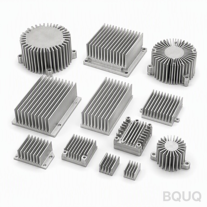
Stamped Heat Sinks vs Extruded: When Does Metal Stamping Make Sense for Cooling?
Metal stamping makes sense for heat sinks when you need high-volume production (over 10,000 units annually), complex fin geometries that extrusion cannot achieve, or significant weight reduction with thermal performance within 85-90% of extruded designs. For applications under 100W of heat dissipation where board space is tight and airflow is directed, stamped copper or aluminum heat sinks offer a cost reduction of 30-50% compared to machined or skived alternatives.
Thermal Performance Comparison: Stamped vs Extruded vs Skived
Stamped heat sinks use thin sheet metal (typically 0.3mm to 1.5mm thickness) formed into fin arrays. The primary thermal limitation is fin efficiency, not material conductivity. At a fin height of 20mm and thickness of 0.5mm, the effective fin efficiency for aluminum (thermal conductivity 205 W/m·K) drops to approximately 78% at typical convection coefficients of 25-50 W/m²·K. This compares to 92-95% for extruded fins of 1.5mm thickness.
| Parameter | Stamped (Al 6061) | Extruded (Al 6063) | Skived (Al 1100) |
| Fin thickness | 0.3-1.0 mm | 1.2-3.0 mm | 0.3-0.8 mm |
| Fin height max | 40 mm | 100 mm | 25 mm |
| Fin pitch minimum | 2.5 mm | 3.5 mm | 1.5 mm |
| Aspect ratio (H/T) | 40:1 | 30:1 | 50:1 |
| Thermal resistance (typical 40x40x20mm, 200 LFM) | 2.8-3.5 °C/W | 2.2-2.8 °C/W | 2.0-2.5 °C/W |
| Tooling cost (one-time) | 800-3,000 USD | 2,000-5,000 USD (die) | 500-2,000 USD |
| Unit cost (10k pcs/year) | 0.35-0.80 USD | 0.50-1.20 USD | 0.60-1.50 USD |
| Lead time (prototype to production) | 2-3 weeks | 4-6 weeks | 1-2 weeks |
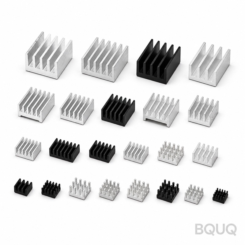
Cost Breakdown: When Volume Justifies Tooling
The stamping process requires a progressive die that can cost between 800 USD for simple flat-fin designs and 3,000 USD for complex louvered or folded geometries. This tooling is amortized over the production run. At 5,000 units per year, tooling adds 0.16-0.60 USD per unit, eroding the material and labor savings. At 50,000 units per year, tooling contributes only 0.02-0.06 USD per unit.
Stamped heat sinks use sheet metal with minimal waste. A typical blanking and forming operation yields 85-90% material utilization, compared to 60-70% for extrusion billets that must be cut and machined. For a 40x40x20mm heat sink weighing 22 grams, raw material cost is approximately 0.12 USD for stamped versus 0.18 USD for extruded plus 0.08 USD for secondary machining.
Secondary operations tell the larger story. Stamped heat sinks integrate mounting clips, spring tabs, and alignment pins directly into the stamping die, eliminating separate fastener costs of 0.05-0.15 USD per unit. Extruded heat sinks often require tapping holes (0.10-0.20 USD each) or adhesive bonding of clips. For high-volume consumer electronics, these per-unit savings of 0.20-0.40 USD quickly outweigh the tooling investment.
Design Rules for Stamped Heat Sink Geometry
Stamping imposes specific geometric constraints that engineers must respect to avoid scrapped tooling and production delays. Minimum bend radius for aluminum 5052 (the most common stamped heat sink alloy) is 1.0 times material thickness. For 0.5mm sheet, this means no bend radius below 0.5mm. Tighter radii cause cracking at the grain boundaries, particularly along the rolling direction.
Fin height is limited by draw depth in a single operation. For a 0.5mm aluminum sheet, the maximum draw depth is 15mm without intermediate annealing. Beyond this, you require multi-stage forming that increases cycle time from 1,200 parts per hour to 400 parts per hour. If your design requires fins over 30mm, consider a folded-fin assembly where individual stamped fins are brazed or mechanically staked to a baseplate.
Recommended stamped heat sink envelope:
| Design Parameter | Recommended Range | Maximum Limit |
| Sheet thickness | 0.4-0.8 mm | 1.5 mm |
| Fin pitch | 3.0-5.0 mm | 2.5 mm |
| Fin height | 8-20 mm | 40 mm (folded) |
| Overall footprint | 10x10 to 150x150 mm | 200x200 mm |
| Flatness tolerance | 0.1 mm over 100mm | 0.2 mm |
| Hole tolerance (pierced) | 0.05 mm | 0.10 mm |
| Bend angle tolerance | 0.5 degrees | 1.0 degree |
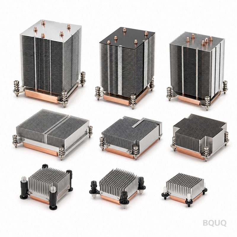
Material Selection: Aluminum Alloys and Copper
Aluminum 5052-H32 is the workhorse for stamped heat sinks. It offers a yield strength of 193 MPa, allowing thin sections to maintain rigidity without springback issues. Thermal conductivity is 138 W/m·K, which is 67% of pure copper but sufficient for most forced-convection applications below 75°C junction temperature.
For high-performance LED drivers and power modules exceeding 150W, stamped copper (C11000, conductivity 391 W/m·K) becomes viable. Copper stamping requires 2-3 times more tonnage than aluminum for the same geometry, increasing tooling wear. A progressive die for copper typically lasts 500,000 strokes versus 1,500,000 for aluminum before requiring re-sharpening. The per-unit tooling amortization increases by 0.03-0.08 USD, but thermal resistance drops by 35-40% compared to aluminum at the same fin geometry.
Surface finishing is critical for stamped heat sinks. The natural oxide layer on aluminum (2-4 nm thickness) adds negligible thermal resistance. However, if you specify black anodizing for emissivity (0.85 versus 0.10 bare), keep coating thickness at 8-12 microns. Thicker anodized layers above 25 microns reduce thermal conductivity through the fin by up to 15% due to the porous, non-conductive oxide structure.
Application Thresholds: Where Stamping Wins and Loses
Stamped heat sinks excel in three specific scenarios. First, LED lighting arrays where 30-80W must be dissipated across a large board area with low profile constraints. A 100x60mm stamped heat sink with 10mm fins achieves 1.8°C/W at 300 LFM airflow, fitting within a 12mm enclosure height. Extrusion cannot reach this height, and die-casting would require expensive molds.
Second, automotive electronics under the hood where vibration resistance matters. Stamped fins with integral spring clips survive 10G random vibration testing without loosening, whereas extruded heat sinks bonded with thermal adhesive have a documented failure rate of 2-4% over 10 years. The mechanical interlock from stamping is inherently more reliable.
Third, telecommunications equipment with high-frequency switching components. The thin fins of a stamped heat sink reduce parasitic capacitance between adjacent fins by 30% compared to thick extruded fins, minimizing electromagnetic interference at frequencies above 1GHz.
Stamping loses to extrusion when thermal density exceeds 10W/cm² of baseplate area. At this level, conduction through the thin base (0.5-1.0mm) becomes the bottleneck, and you need the 3-5mm base thickness of an extruded profile. Stamping also loses for very tall fins above 40mm, where aspect ratio limits cause fin tip temperatures to exceed base temperatures by more than 15°C.
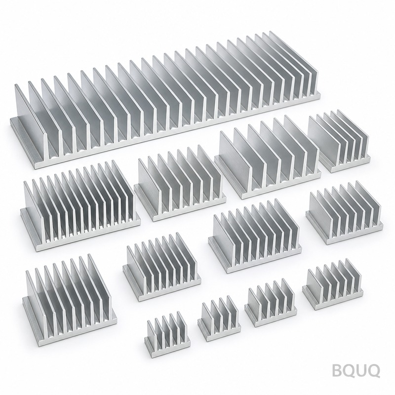
Production Reality: Lead Times, Tolerances, and Quality Control
At BQUQ, our stamping lines operate at 300-1,200 strokes per minute depending on part complexity. A typical heat sink with 12 fins and two pierced mounting holes runs at 600 strokes per minute, yielding a cycle time of 0.1 seconds per part. For 10,000 parts, production takes 17 minutes plus 2 hours of setup and inspection.
Dimensional tolerances are held tighter than most engineers expect. Our standard stamping tolerance for fin-to-fin spacing is 0.05mm, and overall flatness is 0.1mm over a 100mm length. We verify these with CMM inspection on every first article and then at 2-hour intervals during production. Process capability (Cpk) is maintained above 1.33 for all critical dimensions.
Lead time breakdown for a stamped heat sink project:
| Process Stage | Duration (Working Days) |
| DFM review and quote | 1-2 days |
| Tooling design and fabrication | 7-10 days |
| First article samples | 2-3 days |
| Customer approval | 3-5 days |
| Production run (10k parts) | 3-5 days |
| Surface finishing (if required) | 2-3 days |
| Total lead time | 18-28 days |
FAQ-Style Engineering Tips
What is the minimum order quantity for economical stamping? For tooling amortization under 10% of part cost, order at least 8,000-10,000 units. Below 3,000 units, consider skived or bonded-fin assemblies instead.
Can stamped heat sinks be combined with heat pipes? Yes, but design the baseplate with a flat pocket of 0.1mm depth to seat the heat pipe. Use thermally conductive epoxy with 3 W/m·K conductivity to bond the pipe, and crimp the stamped fins around the pipe for mechanical retention.
How do I specify a stamped heat sink in my CAD drawing? Call out material (Al 5052-H32 or C11000), sheet thickness, fin count, fin pitch, overall dimensions, bend radius, and surface finish. Add a note for burr direction and maximum burr height (0.05mm standard). Include flatness tolerance and hole position tolerances per ASME Y14.5.
What is the maximum operating temperature for stamped aluminum? Continuous operation at 150°C is acceptable, but above 200°C the H32 temper begins to over-age, reducing yield strength from 193 MPa to 150 MPa. For sustained temperatures above 200°C, specify 5052-O (annealed) or switch to copper.
Does the thermal interface material affect stamped heat sink performance? The thin base of a stamped heat sink (0.5-1.0mm) flexes more than a thick extruded base. Use a phase-change material or thermal pad with 0.2mm minimum thickness to accommodate baseplate deflection of up to 0.05mm under mounting pressure. Avoid thin grease films that pump out under flexing.
For your next thermal management challenge, evaluate stamped heat sinks early in the design phase. Send us your mechanical drawings, power dissipation requirements, and airflow constraints for a free DFM review. Our engineering team responds within 12 hours with a stamped versus extruded cost and thermal comparison tailored to your production volume. Email your files to sc@bquq.com or contact us on WhatsApp at +86 13713157787. Visit www.bquq.com to view our stamping capabilities and case studies.
Related Articles
- Thermal Management for High Brightness LEDs with Heat Sinks
- Best Copper Heat Sinks for CPU Overclocking in 2025
- New energy vehicle IGBT heat dissipation, heat sink reliability engineering, heat pipe and temperature plate integrated heat sink, surface treatment and heat radiation enhancement: anodic oxidation, black coating and micro-nano structure, graphene/3D printing/intelligent thermal management: 2030 heat sink technology roadmap


