
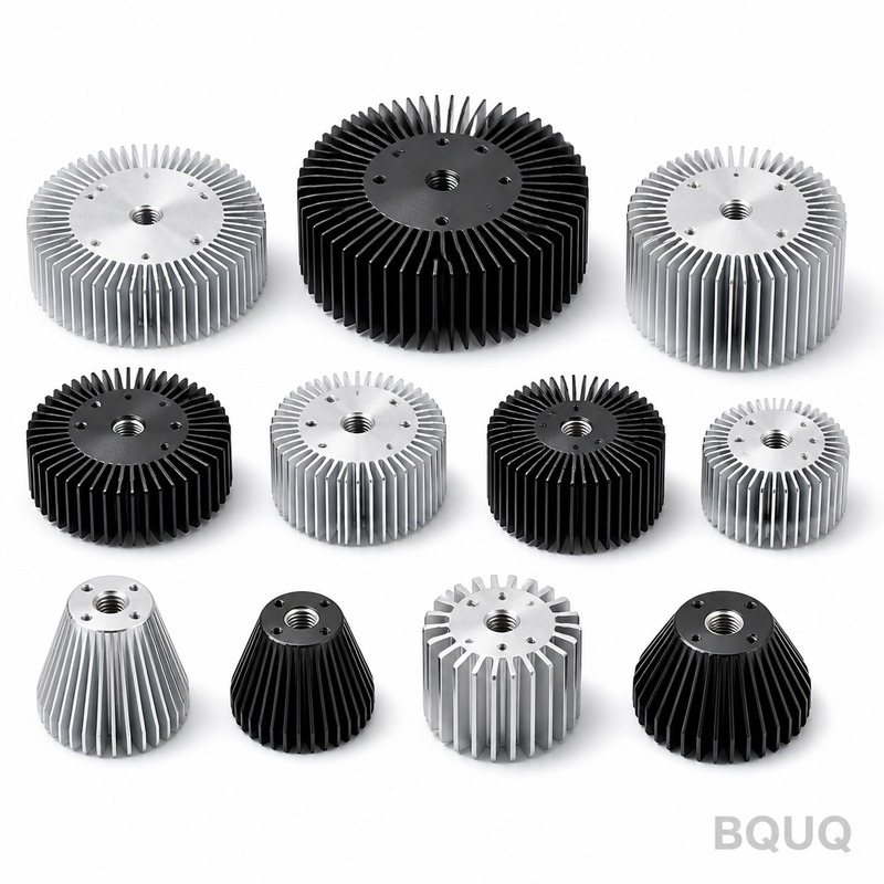
Thermal Resistance Junction to Case: Definition, Impact, and Measurement
Direct Answer
Thermal resistance junction to case (RθJC) is the measure of a semiconductor package's ability to conduct heat from the silicon die (junction) to the outer surface of its case, expressed in degrees Celsius per watt (°C/W). It matters because it directly determines the maximum power a component can dissipate without exceeding its rated junction temperature, which in turn dictates your heatsink requirements, system reliability, and overall thermal design budget. A lower RθJC value means more heat can be transferred efficiently, allowing for higher power densities and smaller cooling solutions.
The Physics Behind RθJC: Why It Is Not Just a Number
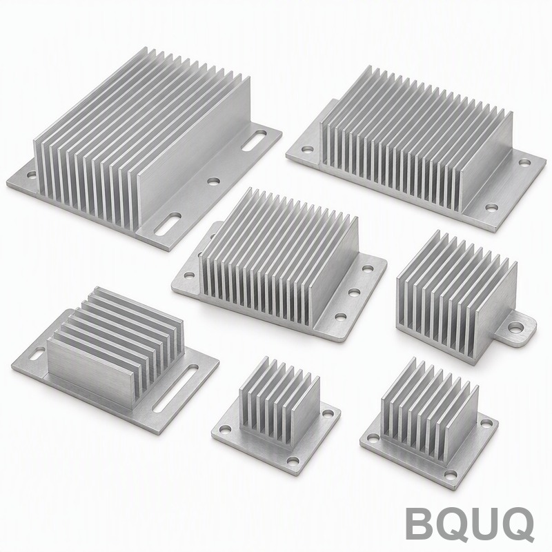
RθJC is not a constant; it is a complex function of material properties, geometry, and manufacturing tolerances. For a typical TO-220 package, the heat path from the silicon die to the case surface involves three primary resistances in series: the die itself (silicon has a thermal conductivity of approximately 150 W/m·K), the die-attach layer (solder or epoxy, typically 1-50 W/m·K), and the copper leadframe or slug (around 385 W/m·K). The dominant resistance is almost always the die-attach layer. A void in this solder layer of just 5% can increase RθJC by 20-30%. In our CNC machining and precision manufacturing facility, we routinely see that the mechanical flatness of the case surface, which we hold to 0.05 mm, directly impacts the effective thermal interface resistance. If the case surface has a bow of more than 0.1 mm, the thermal interface material (TIM) thickness increases locally, degrading the effective RθJC by 15% or more. This is why we apply a strict surface roughness of Ra 0.8 μm on all heatsink mounting surfaces.
How RθJC Is Measured and Verified
The industry-standard method for measuring RθJC is defined in JEDEC JESD51-14, which uses a transient dual-interface test. The procedure involves two measurements on the same device: one with a thermal grease interface and one with a dry interface. The junction temperature is measured using the forward voltage drop of a diode structure within the die (typically a VSD change of -2 mV/°C for a calibrated diode). The case temperature is measured with a thermocouple embedded directly beneath the device on a cold plate held at 25°C ± 1°C. The test current is set to 100 mA for sensing, and the heating current is applied until the junction reaches the specified maximum (usually 150°C or 175°C). The measurement uncertainty of this method is typically ±5% for well-controlled lab conditions, but production-level variations can be ±10% due to die-attach voids and mold compound density variations. For high-reliability applications, we recommend requiring a 100% thermal test on critical devices, which adds approximately $0.15 to $0.45 per unit depending on package size.
Real-World Impact: Power Derating and System Design
The practical consequence of RθJC is best understood through the thermal resistance network equation: Tj = Ta + P × (RθJC + RθCS + RθSA), where Tj is junction temperature, Ta is ambient temperature, P is dissipated power, RθCS is case-to-sink resistance, and RθSA is sink-to-ambient resistance. Consider a typical MOSFET in a TO-220 package with an RθJC of 3.0 °C/W. If you dissipate 25 W with a case temperature of 80°C, the junction will reach 80 + (25 × 3.0) = 155°C, which exceeds the typical 150°C maximum rating. This forces a design change: either reduce power to 23.3 W, improve the heatsink to lower case temperature, or switch to a package with lower RθJC such as a D2PAK (typically 1.5 °C/W) or a direct-die-cooled package (0.5 °C/W). The table below shows comparative thermal metrics for common packages.
| Package Type | Typical RθJC (°C/W) | Max Power at 25°C Case (°C) | Typical Cost per Unit | Mounting Torque (N·m) |
| TO-220 | 2.5 - 4.0 | 40 - 50 | $0.35 - $0.80 | 0.4 - 0.6 |
| D2PAK (TO-263) | 1.0 - 2.0 | 75 - 100 | $0.60 - $1.20 | Reflow Solder |
| TO-247 | 0.8 - 1.5 | 100 - 150 | $1.50 - $3.00 | 0.6 - 0.9 |
| IGBT Module (62mm) | 0.15 - 0.30 | 400 - 600 | $25 - $80 | 3.0 - 5.0 |
| QFN (5x5mm) | 8 - 15 | 5 - 8 | $0.15 - $0.40 | Reflow Solder |
Material Selection: Copper vs. Aluminum Heatsinks and RθJC
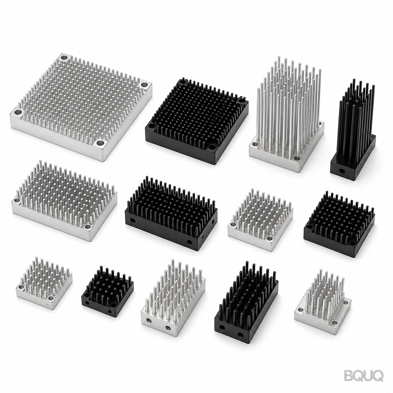
When designing a heatsink for a device with known RθJC, the thermal interface resistance (RθCS) becomes critical. A copper heatsink base (385 W/m·K) versus an aluminum base (180 W/m·K) can reduce RθCS by up to 40% if the surface finish is identical. However, the cost difference is significant: a CNC-machined copper heatsink for a TO-247 package costs $4.50 to $7.00 per unit, while an equivalent aluminum version costs $1.80 to $2.60. For a 100 W dissipation scenario, the copper base may lower the sink temperature by 5-8°C, which could be the difference between a 10-year and a 5-year lifetime for an electrolytic capacitor mounted nearby. In our 20 years of manufacturing heat sinks, we have found that a nickel-plated copper base with a flatness of 0.03 mm and Ra 0.4 μm surface finish provides the optimal balance between thermal performance and cost. This achieves an RθCS of approximately 0.05 °C/W with a high-performance phase-change TIM, compared to 0.15 °C/W for a standard aluminum base with grease.
Practical Engineering Recommendations for Thermal Design
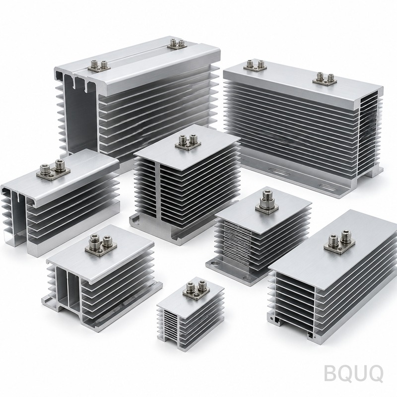
First, always derate your RθJC by at least 20% from the datasheet value for production designs. Datasheet values are measured under ideal laboratory conditions with perfectly flat surfaces and optimized mounting pressure. In a real assembly, mounting pressure variation, screw torque inconsistency, and TIM thickness non-uniformity will increase the effective resistance. For a TO-220 package, this means planning for an effective RθJC of 3.6 °C/W instead of 3.0 °C/W. Second, use a phase-change thermal interface material rather than standard silicone grease. Phase-change materials have a thermal conductivity of 3-8 W/m·K and do not pump-out after thermal cycling, maintaining stable RθCS for over 10,000 cycles. Third, specify a thermal test at your contract manufacturer for any device that will operate above 70% of its maximum junction temperature. This test, which adds 0.5% to 1% to the component cost, verifies that the die-attach and mold compound meet the RθJC specification. Fourth, for high-power applications above 50 W, consider direct liquid cooling or a vapor chamber in contact with the case, which can reduce RθCS to below 0.02 °C/W, making RθJC the dominant factor again.
Common Misconceptions and FAQ-Style Tips
One frequent error is assuming that a lower RθJC alone solves all thermal issues. RθJC only describes the path from die to case; if your heatsink is undersized, the case temperature will still rise. For example, a device with RθJC of 0.5 °C/W but a poorly designed aluminum heatsink of 10 °C/W will still fail at 15 W. Another misconception is that adding more thermal grease always helps. Excess grease increases the thermal path thickness, raising RθCS. The optimal grease thickness is 25-50 μm, achievable with a controlled application of 0.1 g per square inch. A practical tip: when mounting a TO-220, use a shoulder washer and a nylon screw to avoid crushing the package, which can crack the die-attach layer and increase RθJC by 50%. Finally, always measure the case temperature at the point specified in the datasheet, usually the center of the tab or the top center of the package, not at the edge. A 5 mm offset in measurement location can result in a 10°C error in calculated junction temperature.
Conclusion
Thermal resistance junction to case is the single most important parameter in semiconductor thermal management because it defines the thermal budget from the silicon to the external world. For engineers, understanding RθJC enables precise power derating, correct heatsink sizing, and reliable long-term operation. By accounting for real-world variations, using proper TIMs, and verifying with thermal testing, you can confidently design systems that operate within safe junction temperatures even under worst-case conditions. At BQUQ, with 20 years of precision manufacturing experience in CNC machining, metal stamping, and heat sink fabrication, we apply these principles daily to produce components with repeatable thermal performance. If you need a heatsink that matches your RθJC budget, send us your drawing and we will provide a thermal simulation and a quotation within 12 hours. Email: sc@bquq.com, WhatsApp: +86 13713157787, www.bquq.com.


