
Vapor Chamber vs Heat Pipe vs Solid Heat Sink: Key Engineering Differences
Direct Answer: Which Cooling Solution Should You Choose?
The fundamental difference lies in heat spreading mechanism and thermal conductivity. A solid heat sink relies on passive conduction through metal (aluminum 150-200 W/mK, copper 380-400 W/mK), while heat pipes and vapor chambers use phase-change cooling with effective thermal conductivity of 5,000-20,000 W/mK and 10,000-50,000 W/mK respectively. For applications under 50W, solid heat sinks are cost-effective; for 50-250W point-source heat, heat pipes excel; above 250W with large surface area requirements, vapor chambers provide superior two-dimensional spreading. Your choice depends on heat flux density, spatial constraints, and cost tolerance.
Thermal Performance Fundamentals: How Each Technology Works
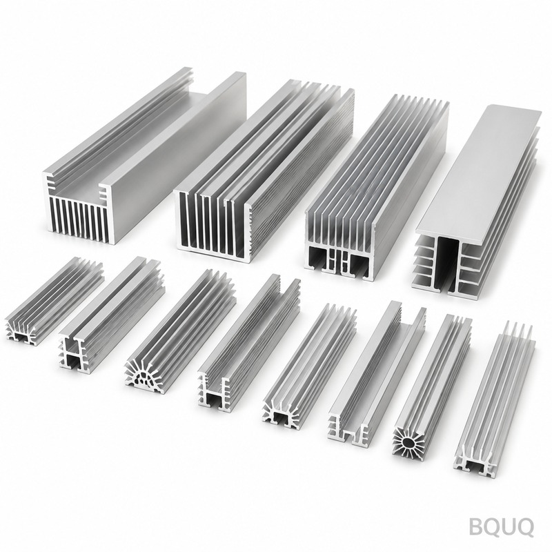
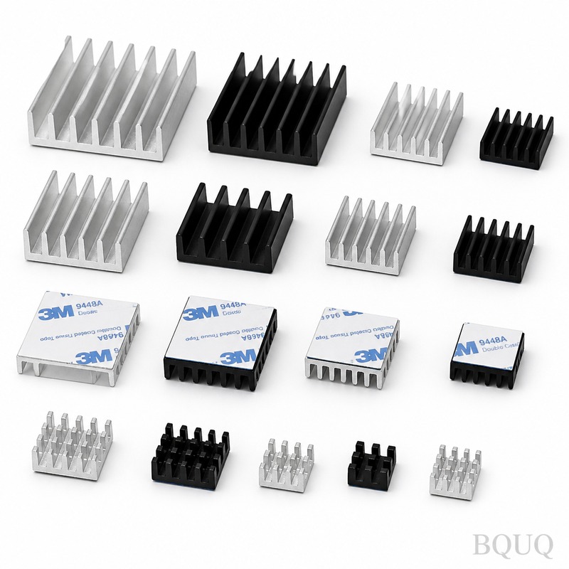
### Solid Heat Sink (Conduction and Convection) A solid heat sink transfers heat via direct metal conduction from the heat source to extended fins, then dissipates it through natural or forced convection. The thermal resistance path is: junction to base (spreading resistance), base to fin (conduction), fin to air (convection). For a 40mm x 40mm aluminum base with 20mm fin height, typical thermal resistance is 2.5-4.5 °C/W under natural convection at 5W load. Under forced airflow of 2 m/s, resistance drops to 1.0-2.0 °C/W.
### Heat Pipe (One-Dimensional Phase Change) Heat pipes are sealed copper tubes with a wick structure and working fluid (usually water). Heat evaporates the fluid at the evaporator section, vapor travels to the condenser end, releases latent heat, and capillary action returns liquid via the wick. Effective thermal conductivity reaches 10,000-20,000 W/mK for a 6mm diameter, 200mm length pipe. Maximum heat transport capacity ranges from 20W (3mm diameter) to 150W (8mm diameter) at horizontal orientation. Thermal resistance per pipe is 0.1-0.5 °C/W.
### Vapor Chamber (Two-Dimensional Phase Change) A vapor chamber is essentially a flat heat pipe that spreads heat in both X and Y axes. It consists of a sealed copper enclosure with internal wick structure and water as working fluid. Heat input spreads uniformly across the entire chamber surface within milliseconds. Typical thermal resistance is 0.05-0.25 °C/W for a 60mm x 60mm chamber. Maximum heat flux handling is 300-500 W/cm² at the evaporator, versus 100-200 W/cm² for heat pipes and 20-50 W/cm² for solid copper.
Comparative Engineering Specifications and Data
| Parameter | Solid Heat Sink (Al 6063) | Solid Heat Sink (Cu C1100) | Heat Pipe (6mm dia) | Vapor Chamber (60x60mm) |
| Effective Thermal Conductivity (W/mK) | 150-200 | 380-400 | 10,000-20,000 | 15,000-50,000 |
| Max Heat Flux at Evaporator (W/cm²) | 15-25 | 30-50 | 100-200 | 300-500 |
| Typical Thermal Resistance (°C/W) | 2.5-4.5 | 1.5-3.0 | 0.2-0.5 | 0.08-0.20 |
| Weight (grams for 100g base) | 270 | 890 | 25-35 per pipe | 80-150 per chamber |
| Minimum Thickness (mm) | 3.0 (die cast) | 2.0 (CNC) | 2.5 (flat pressed) | 2.0 (formed) |
| Operating Temperature Range (°C) | -40 to 200 | -40 to 200 | -40 to 120 (water) | -40 to 120 (water) |
| Manufacturing Tolerance (mm) | ±0.10 (die cast) | ±0.05 (CNC) | ±0.10 outer dia | ±0.15 flatness |
| Unit Cost Range (USD, qty 1000) | 0.80-2.50 | 3.00-8.00 | 2.50-6.00 | 8.00-20.00 |
| Lead Time (days) | 7-14 | 5-10 | 10-18 | 15-25 |
Cost and Manufacturing Complexity Analysis
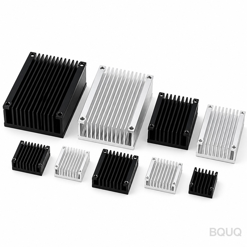
### Solid Heat Sink Cost Structure Extruded aluminum heat sinks (6063-T5) cost $0.80-2.50 per unit at quantities of 1000. Tooling cost for extrusion dies is $500-1,500. CNC machining adds $1.50-4.00 per unit for features like mounting holes and stepped bases. Surface treatment (anodizing, black coating) adds $0.20-0.50 per unit. For copper versions, material cost increases 3-4x, and machining time doubles due to material hardness. Minimum order quantities are low (500 units) due to mature supply chains.
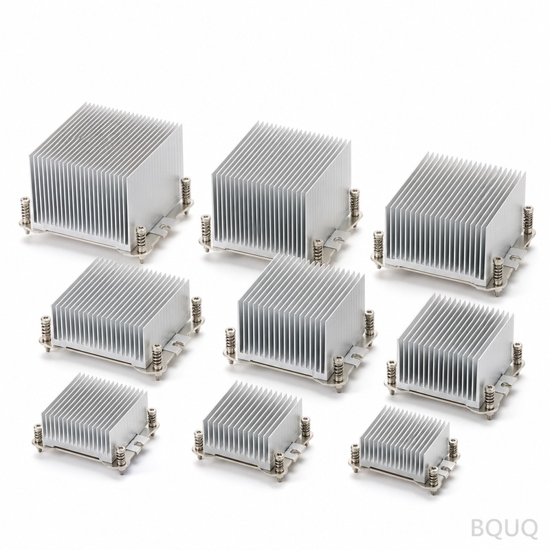
### Heat Pipe Integration Cost A heat pipe assembly includes the pipe itself ($2.50-6.00), aluminum fin stack ($1.00-3.00), and assembly labor ($0.50-1.50). The pipe must be pressed or soldered into a base block, adding $0.80-2.00 per unit. Total assembly cost ranges $5.00-12.00 per unit. Critical tolerance: pipe outer diameter ±0.10mm, base groove depth ±0.05mm to ensure proper thermal contact. Thermal interface material (TIM) adds 0.02-0.05mm thickness and $0.10-0.30 per application.
### Vapor Chamber Cost Structure Vapor chambers are the most expensive option. A 60mm x 60mm x 3mm chamber costs $8.00-20.00 at 1000 units. The manufacturing process involves 6-8 steps: forming, welding, wick sintering, filling, sealing, and testing. Each chamber requires vacuum testing for leak rate below 1x10⁻⁸ atm-cc/s. Yield rates are 85-95%, impacting final cost. For custom shapes or embedded heat pipes, add $5.00-15.00 per unit. Tooling for vapor chamber fixtures costs $2,000-5,000.
Application Selection Criteria and Engineering Guidelines
### When to Use Solid Heat Sinks Choose solid heat sinks for applications below 40W total dissipation, where space allows for larger fin surface area. Typical use cases include LED bulbs (5-15W), small power supplies (10-30W), and low-power amplifiers. The advantage is zero maintenance, no fluid leakage risk, and unlimited orientation flexibility. For natural convection, ensure fin spacing of 6-10mm for aluminum, and fin thickness of 1.2-2.0mm. Maximum fin height-to-gap ratio should not exceed 15:1 for effective airflow.
### When to Use Heat Pipes Heat pipes are optimal for 50-250W applications where the heat source must be relocated away from the cooling fins. Common examples: laptop CPUs (25-45W), server CPUs (100-250W), and LED street lights (50-150W). The pipe should be positioned with a 5-10 degree tilt for gravity-assisted return if orientation permits. For horizontal operation, use sintered copper wick (maximum heat transport is 35-40% lower than gravity-assisted). Never bend pipes more than 90 degrees total, and avoid bends within 20mm of the evaporator or condenser sections.
### When to Use Vapor Chambers Select vapor chambers for high heat flux applications above 250W or where the heat source area is smaller than 20% of the available cooling surface. Ideal for GPU modules (250-350W), high-power laser diodes (500W/cm²), and 5G base station RF amplifiers. The vapor chamber spreads heat uniformly, allowing the entire fin base to participate in heat transfer. For best performance, the heat source should be centered on the chamber; off-center placement increases spreading resistance by 15-30%. Ensure the chamber flatness is within 0.15mm across the entire surface for optimal TIM contact.
Thermal Resistance Budget Example: 200W Server CPU
Let us calculate a complete thermal solution for a 200W server CPU (72mm x 72mm package). The junction-to-case resistance is 0.1 °C/W. For a solid copper heat sink (100mm x 100mm base, 50mm fin height, 2 m/s airflow), total sink resistance is 0.25 °C/W. Junction-to-air total: 0.1 + 0.05 (TIM) + 0.25 = 0.40 °C/W. At 200W, temperature rise is 80°C, giving junction temperature of 105°C at 25°C ambient. This exceeds the 95°C limit, so a solid sink fails.
Using two 8mm heat pipes with 0.15 °C/W each in parallel (equivalent resistance 0.075 °C/W) plus an aluminum fin stack with 0.10 °C/W: total sink resistance is 0.175 °C/W. Total: 0.1 + 0.05 + 0.175 = 0.325 °C/W. Temperature rise is 65°C, junction at 90°C, which passes.
Using a 90mm x 90mm vapor chamber with 0.08 °C/W and same fin stack at 0.10 °C/W: sink resistance is 0.18 °C/W. Total 0.33 °C/W, junction at 91°C. The vapor chamber allows a more compact design (25mm lower height) but costs 2-3x more than the heat pipe solution. For this application, heat pipes offer the best cost-performance tradeoff.
FAQ-Style Engineering Tips
### How do I verify vapor chamber or heat pipe performance? Request samples and test with thermocouples at 3 points: heat source, chamber center, and fin base edge. Measure temperature difference under steady-state load. For vapor chambers, the temperature gradient across the surface should be below 3°C for a 60mm chamber at 200W. For heat pipes, check that the evaporator-to-condenser delta T is below 5°C at rated power. Ask suppliers for performance curves at 25%, 50%, 75%, and 100% rated capacity.
### What are the failure modes for phase-change devices? The primary failure is working fluid leakage, which causes permanent performance degradation. This can occur if the seal is compromised or the pipe is punctured during assembly. Second is wick dry-out, where heat input exceeds capillary pumping capacity, causing the evaporator to overheat rapidly. For vapor chambers, deformation under clamping pressure can crush the internal wick structure. Always specify a pressure limit and use a rigid backing plate.
### Can I combine these technologies? Yes, hybrid solutions are common. A vapor chamber with embedded heat pipes can handle 400W+ from multiple sources. Solid base with heat pipes is the most economical for 100W range. When combining, ensure thermal expansion coefficients are compatible (copper pipes in aluminum bases require interference fit of 0.02-0.05mm). Use thermally conductive epoxy or solder with melting point above 150°C for reliable joints.
Conclusion and Design Recommendation
Select your cooling technology based on heat flux density first, then spatial constraints, then cost. For heat flux below 25 W/cm² and power under 40W, use extruded aluminum solid heat sinks. For 25-100 W/cm² and 50-250W, integrate 6mm or 8mm heat pipes into an aluminum fin stack. For heat flux above 100 W/cm² or power above 250W with limited footprint, invest in vapor chambers. Always prototype and thermal-test your final assembly under worst-case ambient conditions. The 20-30% higher cost of phase-change solutions is justified when it prevents thermal throttling or premature component failure in high-reliability applications.
For your specific project requirements, BQUQ provides free thermal simulation and design review. Our engineers will analyze your heat source profile, airflow conditions, and space constraints to recommend the optimal solution. We manufacture all three types in-house with 20 years of precision machining experience.
BQUQ offers 12-hour quoting on custom cooling solutions. Send your drawings and thermal requirements to sc@bquq.com or WhatsApp +86 13713157787. Visit www.bquq.com for detailed specifications and case studies.
Related Articles
- Thermal Management for High Brightness LEDs with Heat Sinks
- Stamped Metal vs Die Cast Heat Sinks: Cost & Quality Comparison
- New energy vehicle IGBT heat dissipation, heat sink reliability engineering, heat pipe and temperature plate integrated heat sink, surface treatment and heat radiation enhancement: anodic oxidation, black coating and micro-nano structure, graphene/3D printing/intelligent thermal management: 2030 heat sink technology roadmap


