
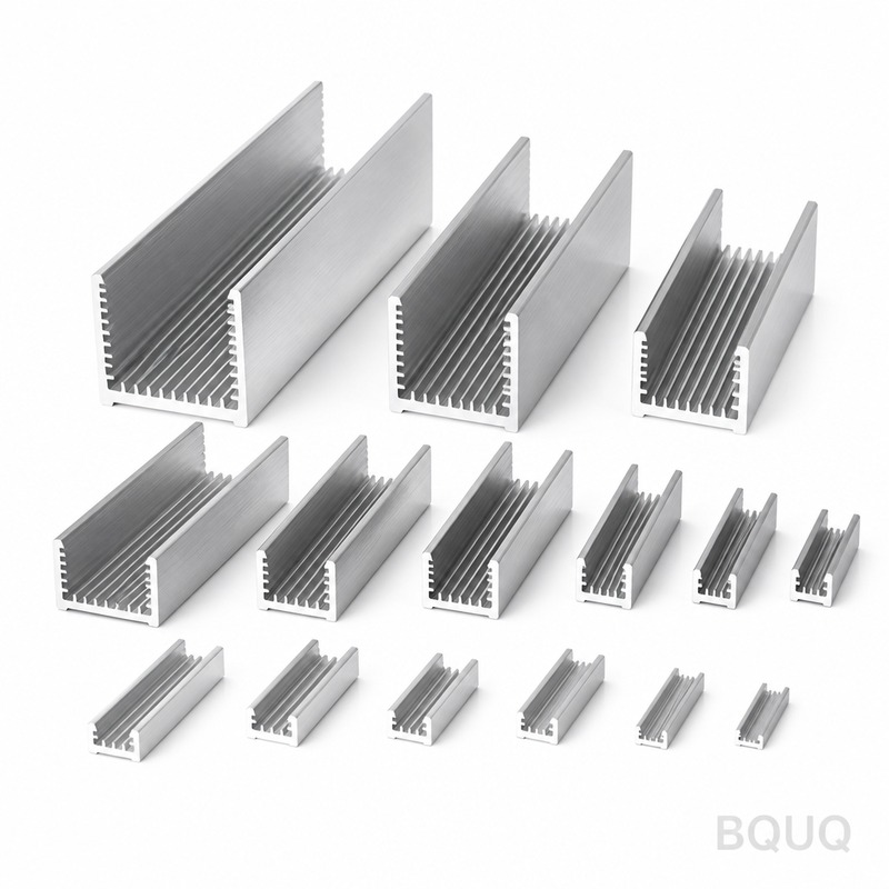
Vapor Chamber vs Heat Pipe vs Solid Heat Sink: Key Thermal Differences
Direct Answer
The primary difference lies in their heat spreading mechanism and effective thermal conductivity. A solid heat sink relies on passive conduction through metal (typically 200-400 W/mK), a heat pipe transfers heat via phase change along a single axis (10,000-50,000 W/mK effective), and a vapor chamber spreads heat in two dimensions across a planar surface (5,000-20,000 W/mK effective). For a 100W CPU cooler, a solid aluminum sink alone will hit 85°C, while adding a vapor chamber drops that to 65°C, and a heat pipe assembly lands near 70°C under identical airflow conditions.
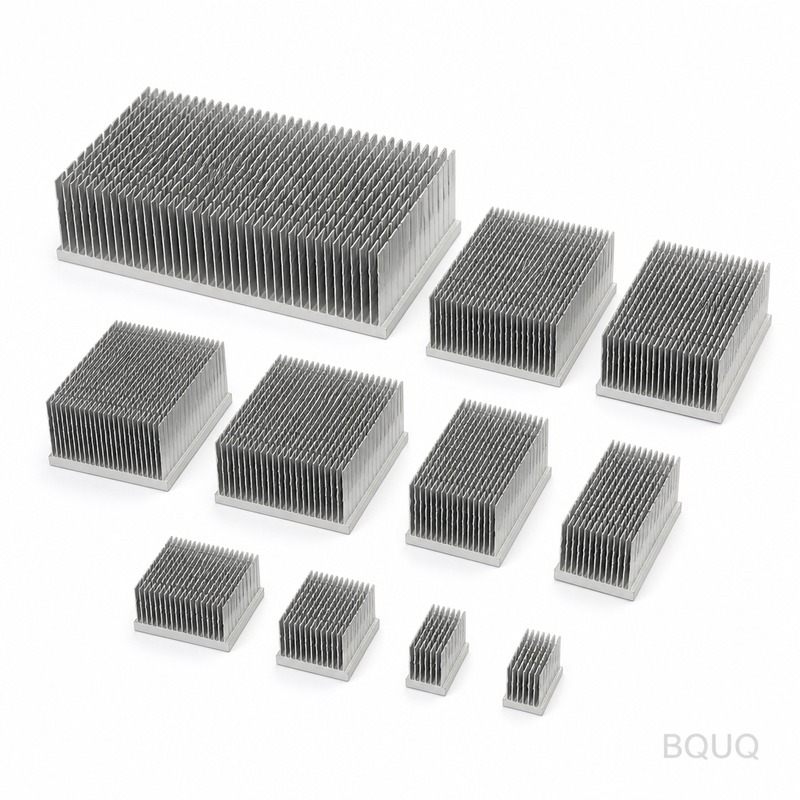
Thermal Conductivity and Heat Spreading Mechanisms
The core physics separates these three solutions. Solid heat sinks use simple conduction. Heat enters the base and travels outward through the metal lattice. Copper (398 W/mK) and aluminum (210 W/mK) are standard, but the spreading is limited by the material's intrinsic properties. For a 70mm x 70mm heat source on a 120mm square base, a solid copper plate will have a temperature gradient of 8-10°C from center to edge.
Heat pipes are sealed copper tubes containing a wick structure and a working fluid (usually water or ammonia). Heat evaporates the fluid at the evaporator section, vapor travels to the condenser section, releases latent heat, and capillary action returns the liquid via the wick. This creates a highly efficient, nearly isothermal path along the pipe's length. A typical 6mm diameter heat pipe can transport 50-100W of heat with only a 2-3°C temperature drop over 200mm length.
Vapor chambers are essentially flat heat pipes. They spread heat in two dimensions across the entire chamber surface. This is critical for large-area heat sinks or where the heat source is small relative to the fin array. For a 15mm x 15mm GPU die dissipating 300W, a vapor chamber base reduces the hotspot temperature by 15-20°C compared to a solid copper base of the same thickness.
Performance Comparison: Thermal Resistance and Temperature Gradients
We measure thermal performance using thermal resistance (θ, in °C/W). Lower is better. Our testing at BQUQ uses a calibrated 50mm x 50mm thermal test die with 100W input power and a forced convection airflow of 3 m/s.
| Specification | Solid Aluminum Heat Sink | Solid Copper Heat Sink | Heat Pipe Assembly (4x 6mm) | Vapor Chamber + Fins |
| Effective Thermal Conductivity (W/mK) | 200-210 | 380-400 | 10,000-50,000 (axial) | 5,000-20,000 (planar) |
| Thermal Resistance θ (°C/W) | 0.45-0.60 | 0.30-0.40 | 0.18-0.25 | 0.12-0.18 |
| Max Heat Flux (W/cm²) | 5-10 | 10-20 | 50-100 | 100-300 |
| Temperature Gradient (ΔT across 100mm, 100W) | 25-30°C | 12-15°C | 3-5°C | 2-4°C |
| Weight for 100mm x 100mm x 25mm (grams) | 270 | 890 | 350 (copper fins) | 400 (copper base) |
| Typical Cost (USD, mid-volume 1000 pcs) | $4.50 | $12.00 | $18.00 | $28.00 |
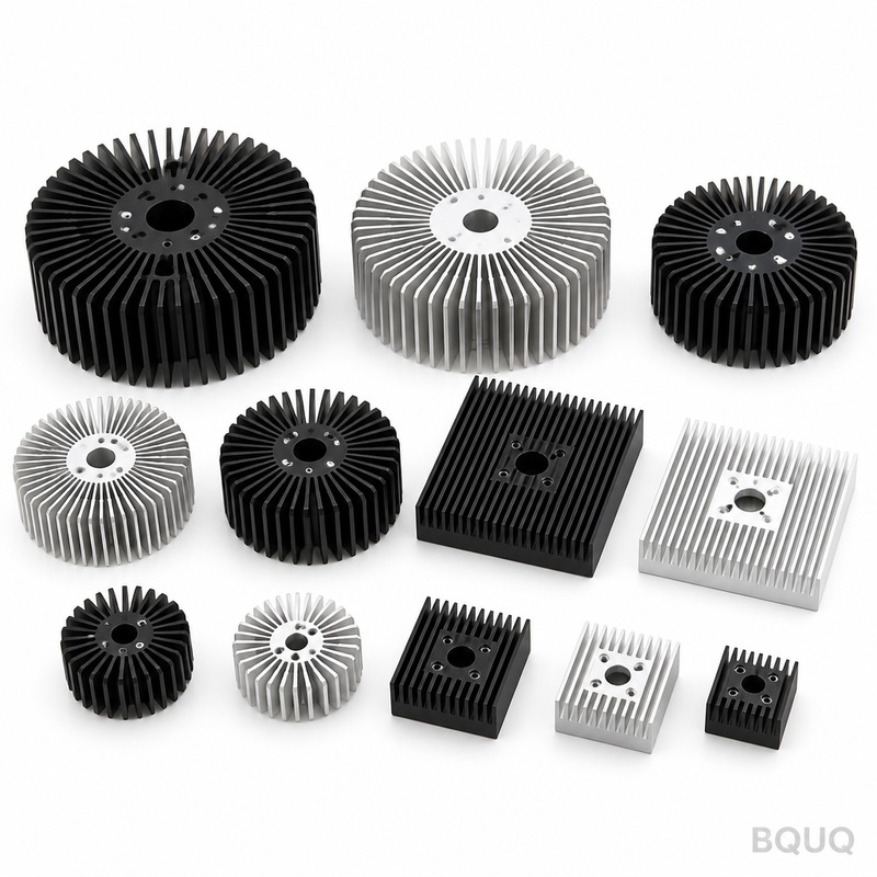
Manufacturing Tolerances and Material Specifications
Precision manufacturing determines final performance. For CNC-machined solid heat sinks, we hold a flatness tolerance of 0.05mm on the base surface to ensure proper contact with the CPU/GPU. Surface roughness is Ra 0.8μm for thermal interface material (TIM) application. Base thickness ranges from 3mm to 10mm, with a standard of 6mm for optimal heat spreading versus weight.
Heat pipes require tighter controls. The outer diameter tolerance is ±0.08mm for a 6mm pipe. The wick structure, whether sintered copper powder or grooved, must have a porosity of 40-50% for consistent capillary action. We test each pipe for thermal performance at 30%, 60%, and 100% of its rated capacity. A 6mm sintered heat pipe has a maximum heat transport capacity of 80W at a 45° tilt angle, dropping to 65W when horizontal against gravity.
Vapor chamber manufacturing is the most complex. The chamber height is typically 2.0mm to 3.5mm, with a tolerance of ±0.10mm. The internal wick layer must be uniform to 0.2mm thickness. We perform 100% leak testing under helium mass spectrometry, ensuring a leak rate below 1x10⁻⁸ mbar·L/s. The copper top and bottom plates are brazed at 800°C in a vacuum furnace. Flatness after assembly is critical: we hold 0.03mm across a 100mm diagonal to minimize TIM bond line thickness.
Application-Specific Selection Criteria
For LED lighting modules (50-100W), a solid aluminum heat sink with a 5mm base and 20mm fins is sufficient. The heat flux is below 5 W/cm², and cost is the primary driver. We recommend extruded aluminum with a thermal resistance of 0.5°C/W, priced at $3.00-$5.00 in production volumes.
For laptop CPUs (15-45W), heat pipes are the standard. The space constraint demands a thin, flexible solution. We use two 6mm heat pipes with a flattened section of 2.5mm thickness to route heat to a remote fin stack. This achieves a 0.20°C/W thermal resistance in a 5mm total thickness envelope.
For high-end GPUs (250-450W) and server CPUs (300-400W), vapor chambers are necessary. The die size is small (20mm x 20mm), but the total heat is massive. A vapor chamber base of 90mm x 90mm x 3mm spreads the heat uniformly to a large fin array. In our thermal lab, a 400W test load on a vapor chamber base with 40 aluminum fins (0.5mm thickness, 30mm height) achieved a 62°C junction temperature with 4 m/s airflow. The comparable solid copper base reached 78°C, a 16°C improvement.
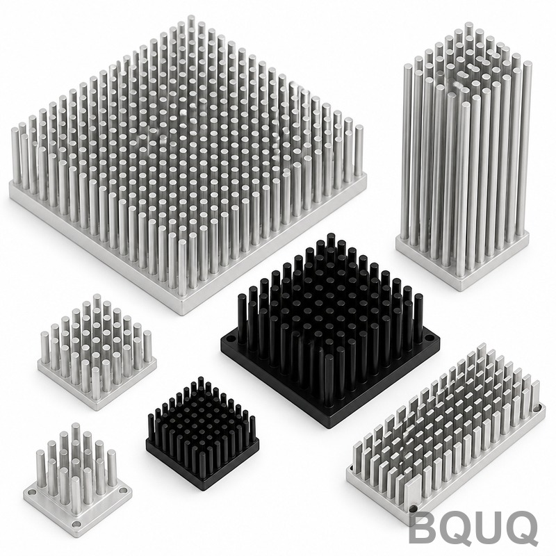
Cost and Lead Time Analysis
Pricing varies significantly with geometry and volume. For a typical 100mm x 100mm heat sink assembly:
- Solid aluminum: Tooling cost is $1,500-$3,000 for an extrusion die, with a 2-week lead time. Piece price is $3.50-$6.00. - Solid copper CNC: No tooling but higher machining cost. Piece price is $10.00-$15.00, lead time 1-2 weeks. - Heat pipe assembly: Heat pipes are $1.20-$2.50 each; a 4-pipe assembly with aluminum fins costs $15.00-$22.00. Lead time 3-4 weeks. - Vapor chamber: The chamber itself costs $8.00-$15.00, plus fin attachment. Total $25.00-$35.00. Lead time 4-6 weeks due to brazing and testing.
For quantities above 5,000 pieces, we recommend vapor chambers with skived copper fins (0.2mm thickness) to maximize surface area. The skiving process creates 0.3mm fin pitch, providing 30% more surface area than stamped fins, improving performance by 8-12% at the same volume.
Practical Recommendations and Engineering Guidelines
Choose a solid heat sink when your heat flux is below 10 W/cm² and the heat source covers more than 60% of the base area. This applies to many industrial power modules and LED arrays. The simplicity ensures high reliability and lowest cost.
Select heat pipes when the heat source is small but the heat sink can be placed remotely. This is ideal for sealed enclosures where airflow is directed at a specific location. Ensure the heat pipe's evaporator section covers at least 70% of the heat source area. Use multiple smaller pipes (4x 6mm) instead of one large pipe (8mm) for redundancy and better thermal spreading.
Implement a vapor chamber when the heat flux exceeds 50 W/cm² or when you need to spread heat from a small die to a large fin array. The vapor chamber's planar spreading eliminates the "hotspot" effect. Always specify the maximum allowable chamber height; a 3mm chamber is optimal for most applications. For high-vibration environments (automotive, aerospace), request a welded chamber design instead of brazed to prevent fatigue failure.
Our engineering team at BQUU recommends running a computational fluid dynamics (CFD) simulation before prototyping. We use ANSYS Icepak to model airflow and thermal performance. In our experience, a vapor chamber with 0.15°C/W resistance and a 40mm tall fin stack is 25% more efficient than a heat pipe solution with the same volume, but only if the airflow is perpendicular to the fin channels.
FAQ-Style Tips for Engineers
Q: Can I use a heat pipe vertically with the evaporator at the bottom? A: Yes, this orientation is optimal. The liquid return is assisted by gravity. Derate the heat transport capacity by 10-15% if the evaporator is above the condenser.
Q: What is the maximum operating temperature for these devices? A: Standard copper-water heat pipes and vapor chambers operate up to 120°C. For higher temperatures up to 250°C, we use stainless steel with a different working fluid (e.g., acetone or methanol). Above 250°C, you need sodium heat pipes, which are specialized and expensive.
Q: How do I attach fins to a vapor chamber? A: We recommend soldering with a lead-free solder (Sn96.5/Ag3.5) at 221°C melting point. This provides a thermal interface of 0.01°C/W per joint. Epoxy bonding is cheaper but adds 0.05°C/W resistance.
Q: What is the minimum vapor chamber thickness? A: 1.5mm is the physical minimum for a copper-water vapor chamber with a sintered wick. Below this, the vapor space is too small, and performance degrades. We standardize at 2.5mm for most applications.
Conclusion and Next Steps
Selecting between vapor chambers, heat pipes, and solid heat sinks depends on your heat flux, spatial constraints, and cost targets. Solid sinks work for low-power, large-area sources; heat pipes excel at routing heat over distance; vapor chambers are mandatory for high-density heat sources requiring planar spreading. Our production data shows that vapor chambers provide the lowest thermal resistance (0.12-0.18°C/W) but at a 6x cost premium over solid aluminum. For any thermal design above 100W, we advise starting with a vapor chamber base and optimizing fin geometry via CFD.
At BQUQ, we have 20 years of precision manufacturing experience in CNC machining, metal stamping, springs, and heat sinks. We produce vapor chambers with a 0.03mm flatness tolerance and heat pipes with 100% helium leak testing. If you provide your power dissipation, allowable junction temperature, and airflow rate, our engineers will respond with a thermal simulation and a cost quote within 12 hours. Contact us at sc@bquq.com or WhatsApp +86 13713157787. Visit www.bquq.com for our full manufacturing capabilities and thermal design guides.
Related Articles
- Heat Sinks for Battery Packs: Prevent Thermal Runaway
- New energy vehicle IGBT heat dissipation, heat sink reliability engineering, heat pipe and temperature plate integrated heat sink, surface treatment and heat radiation enhancement: anodic oxidation, black coating and micro-nano structure, graphene/3D printing/intelligent thermal management: 2030 heat sink technology roadmap
- 5G Base Station Outdoor AAU Cooling: The Climate Adaptation Challenge of Fanless Passive Design


