
What Are the Best Compact Cooling Solutions for Edge AI Thermal Management?
The most effective compact cooling solutions for distributed AI systems combine high-density heat sinks with forced convection, using either miniature blowers or synthetic jets, to manage heat fluxes of 5 to 25 W/cm² within enclosures under 10 liters. For most edge deployments, a hybrid approach—an aluminum or copper vapor chamber base with a 15 mm to 30 mm tall fin stack and a 40 mm x 40 mm blower—delivers the optimal balance of thermal performance (case-to-ambient thermal resistance of 0.5 to 2.0 °C/W), acoustic noise (below 35 dBA), and cost (USD 15 to USD 45 per unit in volume). Passive solutions, such as natural convection heat sinks with heat pipes, are viable only when the total power dissipation is below 25 W and the ambient temperature remains under 45 °C.
What Is the Thermal Challenge Specific to Edge AI Processors?
Edge AI devices, such as NVIDIA Jetson Orin NX (15 to 40 W) and Intel Movidius Myriad X (1 to 2 W), generate concentrated heat in a small footprint. A typical system-on-module (SOM) measures 45 mm x 45 mm, which means a 25 W load translates to a heat flux of approximately 12 W/cm² across the processor die. Unlike data centers with chilled water loops, edge enclosures—such as IP67-rated outdoor cameras or factory PLC cabinets—offer limited airflow and ambient temperatures that can range from -20 °C to 60 °C. The design constraint is not just peak temperature but thermal cycling: repeated expansion and contraction at solder joints (e.g., BGA packages) causes fatigue failure. For a junction-to-case thermal resistance of 0.3 °C/W and a maximum junction temperature of 95 °C, the case must stay below 87.5 °C while dissipating 25 W in a 50 °C ambient.
How Do You Select the Right Heat Sink Geometry for a 10-Liter Enclosure?
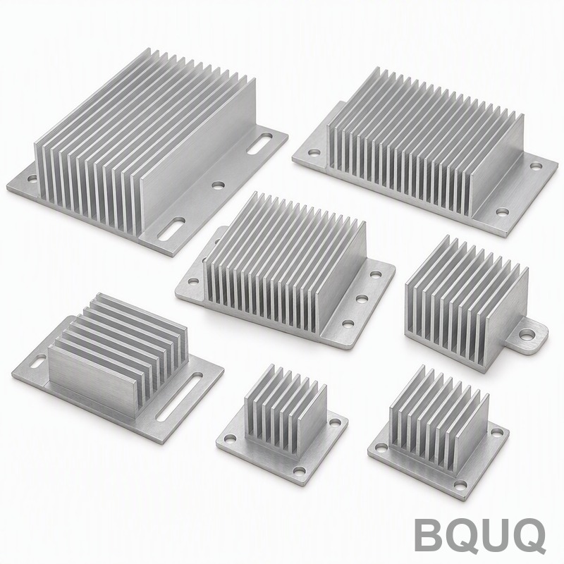
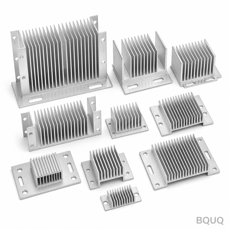
The heat sink geometry is governed by the available pressure drop from the fan or blower and the fin pitch that balances surface area against airflow resistance. For a blower delivering 5 to 10 CFM at 0.2 to 0.5 inches of water static pressure, a fin height of 20 mm, fin thickness of 1.0 mm, and fin pitch of 3.0 mm yields a thermal resistance of 0.8 to 1.2 °C/W for a 60 mm x 60 mm base. Increasing fin height to 30 mm improves resistance by 15% but raises pressure drop by 40%, which may stall a low-power blower. A pin-fin array (2.0 mm diameter pins, 4.0 mm pitch) provides omnidirectional airflow, which is beneficial when the enclosure has multiple inlet vents. For heat fluxes above 15 W/cm², a vapor chamber (0.2 mm copper envelope, 50 mm x 50 mm) spreads heat from a 15 mm x 15 mm die to the entire base, reducing spreading resistance from 1.5 °C/W to 0.3 °C/W compared to solid copper.
Why Are Vapor Chambers Superior to Solid Copper for Distributed AI?
Vapor chambers exploit the latent heat of vaporization of water (2260 kJ/kg), achieving effective thermal conductivity of 5000 to 20000 W/m·K versus 385 W/m·K for copper. In a compact edge device, the processor die is often smaller than the heat sink base, creating a spreading resistance penalty. For a 25 W load on a 10 mm x 10 mm die spread to a 60 mm x 60 mm base, a 3 mm thick solid copper base has a spreading resistance of 1.8 °C/W, while a 2 mm thick vapor chamber reduces this to 0.4 °C/W. This reduction translates to a 35 °C lower junction temperature at the same airflow. However, vapor chambers cost USD 8 to USD 15 more than an equivalent copper base and have a minimum thickness of 2.5 mm to maintain internal wick structure. They also have a maximum heat transport capacity (typically 200 to 400 W for a 50 mm x 50 mm chamber), which is rarely exceeded in edge AI.
Which Cooling Method Works Best for Fanless Edge Enclosures?
For fanless designs, the choice is between natural convection heat sinks, heat pipes, and phase-change materials (PCMs). A natural convection heat sink with a 100 mm x 100 mm base, 40 mm fin height, and 6.0 mm fin pitch achieves 2.5 °C/W in still air, limiting dissipation to 12 W at a 40 °C temperature rise. Heat pipes (6 mm diameter, 150 mm length) can transfer 30 to 50 W horizontally, allowing heat to be moved from the processor to a remote finned surface on the enclosure wall. For intermittent AI workloads—e.g., a vision system running inference for 60 seconds every 5 minutes—a PCM (paraffin wax with a latent heat of 200 kJ/kg, melting at 55 °C) can absorb 20 W for 5 minutes without a temperature rise. The PCM volume required is 20 W x 300 s / (200 kJ/kg x 700 kg/m³) = 0.043 liters, which is feasible in a 0.5-liter cavity. However, PCMs require a re-solidification time of 15 to 30 minutes, so they cannot sustain continuous loads.
How Do You Calculate Airflow Requirements for an Edge AI Enclosure?
The required volumetric airflow (in CFM) is calculated from Q = 1.76 x P / ΔT, where P is the dissipated power in watts and ΔT is the allowable air temperature rise in °C. For a 30 W processor with a maximum 10 °C rise across the heat sink, airflow must be 5.3 CFM. This flow must overcome the pressure drop of the heat sink (0.1 to 0.3 inches of water) plus inlet filters and grilles (0.05 to 0.15 inches of water). A 40 mm x 40 mm x 20 mm blower (e.g., Sunon or Delta) provides 6.5 CFM at 0.3 inches of water, consuming 2.5 W and producing 32 dBA. Doubling the fin density (pitch from 3.0 mm to 1.5 mm) increases surface area by 40% but raises pressure drop to 0.6 inches of water, which reduces blower flow to 3.5 CFM—a net loss in heat transfer. The optimal operating point is where the heat sink pressure drop curve intersects the blower performance curve, typically at 60% to 80% of the blower's free-air flow.
When Should You Use Liquid Cooling in an Edge AI System?
Liquid cooling is justified only when the heat flux exceeds 30 W/cm², the ambient temperature exceeds 55 °C, or the enclosure is sealed (IP68) with no air exchange. A compact liquid loop with a 60 mm x 60 mm cold plate, a 12 V DC pump (2.5 W, 0.5 L/min flow), and a 120 mm x 120 mm radiator with a 120 mm fan can dissipate 100 W with a thermal resistance of 0.1 °C/W to 0.3 °C/W. The total system cost is USD 80 to USD 150 per unit, plus the risk of leakage (MTBF of quick-disconnect fittings is 10000 cycles). For most edge AI applications (e.g., 5G base station edge servers, autonomous vehicle controllers), air cooling with a vapor chamber and a blower is sufficient up to 60 W. Liquid cooling becomes economically viable only when the failure cost of an overheated GPU (USD 500 to USD 2000) exceeds the cooling system cost.
What Are the Real-World Thermal Resistance Targets for Edge AI Heat Sinks?
The following table provides baseline thermal performance targets for common edge AI form factors, based on our 20 years of manufacturing experience in Dongguan.
| Enclosure Volume | Max Power (W) | Heat Sink Type | Thermal Resistance (°C/W) | Airflow Required (CFM) | Typical Cost (USD, 1000 pcs) |
| 0.5 L (camera) | 10 | Aluminum extrusion, 30 mm fin | 2.0 | 1.5 (natural) | 3.5 |
| 2 L (PLC) | 25 | Copper base + aluminum fin, 40 mm blower | 0.8 | 5.0 | 18.0 |
| 5 L (edge server) | 45 | Vapor chamber + pin fin, 60 mm blower | 0.5 | 10.0 | 35.0 |
| 10 L (rugged PC) | 60 | Heat pipe + remote fin stack, dual 60 mm fans | 0.3 | 15.0 | 55.0 |
| Sealed IP68 | 20 | PCM + enclosure wall conduction | 1.5 | 0 (passive) | 40.0 |
How Can You Validate a Compact Cooling Design Before Production?
Thermal validation requires a thermocouple (type T, ±0.5 °C accuracy) mounted on the processor case and a data logger sampling at 1 Hz. Run a steady-state test at maximum power (e.g., 30 W) for 60 minutes until the temperature stabilizes within ±1 °C. The junction temperature is calculated as Tj = Tc + (P x Ψjt), where Ψjt is the junction-to-case thermal resistance from the datasheet (typically 0.2 to 0.5 °C/W). A CFD simulation (e.g., Ansys Icepak) should predict the case temperature within ±5 °C of the measured value; if the discrepancy exceeds this, check the airflow path for recirculation (hot air re-entering the inlet) or bypass (air flowing around the heat sink). For production, use a thermal test fixture that presses a heated cartridge (50 W capacity) against the heat sink base and measures the temperature rise; this fixture can be automated for 100% inspection with a pass/fail threshold of ±10% on thermal resistance.
What Are the Cost Drivers for Custom Edge AI Heat Sinks?
Tooling cost for an extruded aluminum heat sink is USD 800 to USD 2500, with a minimum order quantity of 500 pieces at USD 3 to USD 8 per unit. A die-cast copper base adds USD 3000 to USD 6000 in tooling, but the unit cost is competitive at high volumes (USD 5 to USD 12). Vapor chambers require a custom fixture (USD 2000) and a lead time of 4 to 6 weeks, versus 2 weeks for extrusion. The most significant cost driver is surface treatment: anodizing (USD 1.5 per unit) improves emissivity from 0.1 to 0.8, which is critical for natural convection; nickel plating (USD 2.5 per unit) is used for solderability. For a 25 W edge AI module, the total cooling solution (heat sink + blower + thermal interface material) should cost USD 15 to USD 30 per unit, representing 5% to 10% of the total device cost.
How Do You Choose Between a Blower and an Axial Fan for a 2U Edge Server?
A 2U server chassis (88.9 mm height) restricts heat sink height to 25 mm, which favors a blower that can generate static pressure of 0.4 to 0.8 inches of water to push air through the narrow fin channels. Axial fans (40 mm x 40 mm x 28 mm) provide high flow (15 CFM) but only 0.1 inches of water static pressure, making them suitable for low-resistance heat sinks with fin pitch above 4.0 mm. For a 2U edge server with two 25 W processors, use one 60 mm blower (10 CFM at 0.5 inches water, 38 dBA) positioned at the front of the chassis, directing air across both heat sinks in series. This arrangement yields a total pressure drop of 0.8 inches of water, which the blower can handle at 80% efficiency. If acoustic noise is a concern (below 30 dBA), increase the fin pitch to 4.0 mm and reduce the blower speed by 20%, accepting a 15% higher thermal resistance.
What Is the Role of Thermal Interface Materials in Edge AI Assembly?
Thermal interface materials (TIMs) fill the 10 to 50 micrometer air gap between the processor lid and the heat sink base. A phase-change TIM (e.g., Honeywell PTM7950, 0.05 mm thickness) achieves 0.05 °C·cm²/W thermal impedance, which is 10 times better than a silicone pad (0.5 °C·cm²/W). For a 25 W processor, the TIM contributes 0.2 °C/W with a phase-change material versus 2.0 °C/W with a thick pad—a difference of 45 °C in junction temperature. Liquid metal (gallium-based) offers 0.01 °C·cm²/W but is electrically conductive and requires a nickel-plated surface to avoid corrosion; it is not recommended for edge devices due to pump-out risk under vibration. The recommended TIM for compact cooling is a 0.2 mm graphite pad (thermal conductivity 15 W/m·K) that costs USD 0.30 per unit and can be reworked without cleaning residue.
FAQ
How Much Power Can a Passive Heat Sink Dissipate in a Sealed Enclosure?
A passive heat sink in a sealed enclosure can dissipate 5 to 15 W, depending on the enclosure surface area (0.1 to 0.3 m²) and the maximum allowable internal temperature rise. If the enclosure is metal (aluminum, 2 mm thick), you can achieve 10 W with a 30 °C rise; plastic enclosures limit dissipation to 5 W due to lower thermal conductivity (0.2 W/m·K). For higher power, you must add ventilation or a heat pipe to the enclosure wall.
What Is the Maximum Ambient Temperature for Air-Cooled Edge AI?
The maximum ambient temperature for air-cooled edge AI is 55 °C, assuming a 25 W processor, a case temperature limit of 85 °C, and a heat sink thermal resistance of 1.0 °C/W. Above 55 °C, the temperature differential (85 - 55 = 30 °C) is insufficient to reject 25 W with a reasonable airflow of 5 CFM. For ambient temperatures up to 70 °C, you need liquid cooling or a vapor chamber with a larger finned area.
When Should I Use a Heat Pipe Instead of a Vapor Chamber?
Use a heat pipe when the heat source is more than 50 mm away from the finned heat rejection area, such as in a sealed enclosure where the processor is on a vertical PCB and the fins are on the top cover. A 6 mm heat pipe can bend 90 degrees with a radius of 25 mm, losing only 5% capacity per bend. Use a vapor chamber when the heat source is directly under the heat sink base and spreading resistance is the main concern.
Which Blower Size Is Optimal for a 30 W Edge AI Module?
A 40 mm x 40 mm x 20 mm blower is optimal for a 30 W module, providing 6.5 CFM at 0.3 inches of water static pressure and consuming 2.5 W. It fits within a 2U height envelope and produces 32 dBA, which is acceptable for industrial settings. Larger blowers (60 mm) reduce noise to 25 dBA but require 40 mm of clearance, which is not available in compact enclosures.
Can I Use a Standard CPU Cooler for an Edge AI Processor?
Yes, but only if the cooler height is under 40 mm and the mounting pattern matches the processor (e.g., 50 mm x 50 mm). Standard CPU coolers for desktops have 80 mm to 120 mm heat sink heights and are designed for 65 W to 125 W loads, which is oversized for edge AI. A low-profile cooler (35 mm height, 80 mm fan) can handle 40 W but costs USD 25 to USD 40, whereas a custom heat sink and blower costs USD 15 to USD 20.
What Is the Lead Time for Custom Vapor Chamber Samples?
Custom vapor chamber samples have a lead time of 3 to 4 weeks, including tooling fabrication (fixture) and leak testing. Production quantities (1000+ pieces) require an additional 2 to 3 weeks for the sintering process and quality inspection. We recommend ordering samples at least 6 weeks before your planned production start to allow for thermal validation and design iterations.
How Do I Test for Thermal Fatigue in Edge AI Enclosures?
Thermal fatigue testing involves cycling the processor power from 0% to 100% every 10 minutes for 1000 cycles, while monitoring the case temperature. The pass criterion is a junction temperature increase of less than 5 °C from the first cycle to the last, indicating no degradation in the TIM or solder joints. Use a thermal shock chamber (from -40 °C to 85 °C) for accelerated testing, with a ramp rate of 10 °C/min.
Conclusion
Compact cooling for edge AI demands a systems-level approach: calculate the heat flux, select a vapor chamber or heat pipe for spreading, size a blower for the available pressure drop, and validate with thermocouple measurements. For most distributed AI workloads under 60 W, a vapor chamber base with a 20 mm pin-fin stack and a 40 mm blower provides the best balance of performance, cost, and reliability in a 2-liter enclosure. Passive cooling is limited to 15 W, and liquid cooling is reserved for extreme heat fluxes above 30 W/cm². Partnering with a manufacturer that has both thermal simulation and CNC machining capabilities ensures your heat sink is optimized for real-world airflow, not just the datasheet. For a rapid assessment of your edge AI thermal requirements, send us your power map and enclosure dimensions. We provide a 12-hour quoting service with detailed thermal resistance calculations and DFM feedback.
| Email: sc@bquq.com | WhatsApp: +86 13713157787 | www.bquq.com |
Related Articles
- AI simulation and intelligent manufacturing: the heat sink industry has gone from "trial and proof" to "one time right"
- When liquid cooling becomes mainstream: the evolving role of hardware heat sinks in the data center era
- From Macro Base Station to Edge Box: Transforming Heat Sink Requirements in Communication Network Evolution


