
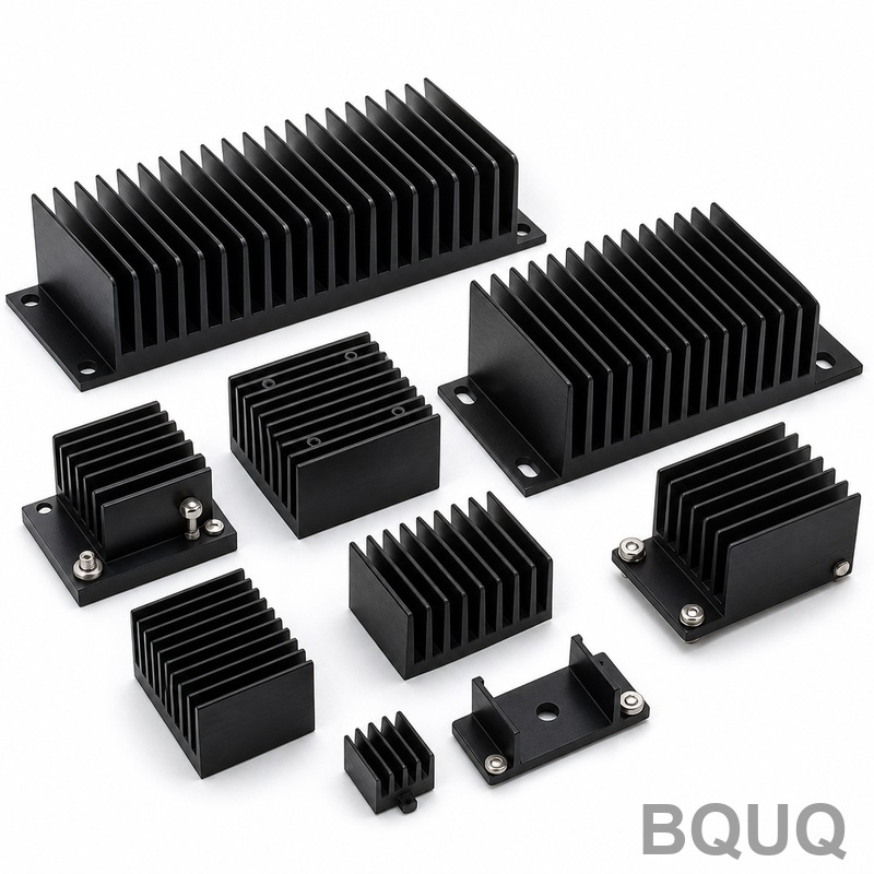
What Are the Standard Heat Sink Mounting Hole Patterns and Best Practices?
The most common heat sink mounting hole patterns are 2-hole and 4-hole configurations on a standard 5.08 mm (0.2 inch) pitch grid, with M3 or #6-32 screws being the industry default for most semiconductor packages. For TO-220 and TO-247 packages, the hole spacing is typically 2.54 mm or 5.08 mm between centers, while larger custom heat sinks for CPUs or IGBTs often use a 50 mm x 50 mm or 75 mm x 75 mm pattern with M4 hardware. The best practice is to match the hole pattern to the component datasheet, use a thermal interface material with a target clamping pressure of 20 to 50 psi, and always specify a flatness tolerance of 0.05 mm across the mounting surface.
What Are the Common Mounting Hole Standards for TO-220 and TO-247 Packages?
For TO-220 packages, the standard hole pattern is a single hole of 3.2 mm diameter or a two-hole pattern with centers spaced 2.54 mm apart, using M3 screws with a recommended torque of 0.4 to 0.6 Nm. TO-247 packages typically require a two-hole pattern with 5.08 mm spacing, accommodating M3 or M4 screws, with a recommended mounting torque of 0.6 to 0.8 Nm. These standards originate from JEDEC specifications, and deviation from them risks mechanical stress on the semiconductor die, leading to premature failure. For power modules like the SEMITRANS or SKiM series, the hole pattern often uses a 4-hole configuration on a 34 mm x 20 mm or 45 mm x 30 mm rectangle, requiring M4 or M5 screws.
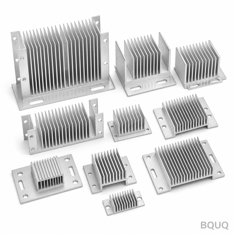
How Should You Determine the Correct Hole Size and Clearance?
The mounting hole diameter must account for the screw size plus a clearance allowance. For an M3 screw, the recommended clearance hole is 3.4 mm for standard applications, but 3.2 mm if you require precise alignment with a press-fit insert. For M4 screws, use a 4.5 mm clearance hole. For self-tapping screws into aluminum heat sinks, the pilot hole should be 2.5 mm for M3 and 3.3 mm for M4, with a minimum thread engagement of 1.5 times the screw diameter. If you are using a shoulder screw or standoff, the hole must be oversized by 0.1 mm to 0.2 mm to prevent binding due to thermal expansion, which typically causes a linear expansion of 0.023 mm per 100 mm length for a 50°C temperature rise on an aluminum base.
Why Does Hole Pattern Geometry Affect Thermal Performance?
The hole pattern directly influences the contact pressure distribution across the heat sink base, and non-uniform pressure creates air gaps that act as thermal insulators. A 4-hole pattern on a 50 mm x 50 mm grid provides a more uniform pressure map, typically achieving a thermal resistance of 0.15 °C/W, compared to a 2-hole pattern which may yield 0.25 °C/W for the same heat sink. Additionally, holes drilled too close to the heat sink edge (less than 5 mm from the edge) reduce the structural integrity of the base, causing warpage during CNC machining or stamping, which increases the thermal interface resistance by up to 30%. BQUQ recommends maintaining a minimum wall thickness of 3 mm between the hole edge and the heat sink boundary for optimal rigidity.
Which Screw Materials and Finishes Are Best for Heat Sink Mounting?
For aluminum heat sinks, the best screw material is stainless steel (A2-70 or A4-80) to prevent galvanic corrosion, which occurs when dissimilar metals contact in humid environments. Zinc-plated carbon steel screws are acceptable for indoor use but have a lower corrosion threshold, rated for only 72 hours of salt spray testing, while stainless steel exceeds 500 hours. For applications requiring high thermal conductivity through the screw, copper screws with nickel plating are used, though they cost approximately USD 0.18 per unit versus USD 0.03 for zinc-plated steel. The screw finish should be smooth, with a thread tolerance of 6g for the screw and 6H for the tapped hole, ensuring a proper fit without galling during repeated assembly cycles.
How Much Does Custom Tooling Cost for Non-Standard Hole Patterns?
Custom tooling for a non-standard hole pattern on a stamped heat sink, such as a 25 mm x 25 mm pattern with a 6.5 mm center hole, costs between USD 800 and USD 1,500 for a progressive die. For CNC machined heat sinks, the programming and fixturing cost for a custom pattern is lower, typically USD 150 to USD 400, but the per-unit cost increases due to longer cycle times, adding USD 0.05 to USD 0.15 per part. If you require a unique thread form, such as an M2.5 pitch, a custom tap costs approximately USD 60, and the lead time for tooling is 5 to 7 business days at BQUQ, while standard M3 and M4 taps are in stock and incur no additional cost.
When Should You Use Through-Holes Versus Blind Tapped Holes?
Through-holes are preferred when the heat sink is mounted to a chassis or PCB with access from both sides, as they allow for faster assembly and lower cost, reducing machining time by 15% compared to blind holes. Blind tapped holes, typically with a depth of 8 mm to 10 mm for M3 screws, are necessary when the heat sink has a finned backside or when a clean external surface is required for aesthetics. Use blind holes when the heat sink thickness is less than 12 mm, as through-holes would compromise the structural integrity and reduce the effective cooling area on the opposite side, which can lower the convective heat transfer coefficient by 5% to 10%.
What Are the Best Practices for Thermal Interface Material Application with Hole Patterns?
The thermal interface material (TIM) must be cut or dispensed to avoid covering the mounting holes, as excess TIM can cause screw slippage and reduce clamping force. For a 4-hole pattern on a 50 mm x 50 mm grid, a pre-cut TIM pad of 45 mm x 45 mm with 5 mm diameter cutouts at each hole location is recommended, ensuring a 2 mm clearance from the hole edge. Apply a consistent TIM thickness of 0.05 mm to 0.1 mm, and achieve a clamping torque of 0.6 Nm for M3 screws, which produces a contact pressure of approximately 30 psi, the optimal range for silicone-based TIMs. For phase-change materials, the recommended pressure is higher, at 40 to 50 psi, requiring a torque of 0.8 Nm, and the heat sink must be pre-heated to 60°C during installation to ensure proper wetting.
What Is the Recommended Hole Pattern for High-Power IGBT and CPU Heat Sinks?
| Package Type | Hole Count | Hole Spacing (mm) | Screw Size | Recommended Torque (Nm) | Thermal Resistance (°C/W) |
| TO-220 | 1 or 2 | 2.54 | M3 | 0.4 - 0.6 | 0.20 - 0.30 |
| TO-247 | 2 | 5.08 | M3 or M4 | 0.6 - 0.8 | 0.15 - 0.25 |
| IGBT Module (34 mm) | 4 | 34 x 20 | M4 | 1.2 - 1.5 | 0.08 - 0.12 |
| CPU (LGA2011) | 4 | 75 x 75 | M4 | 0.8 - 1.0 | 0.05 - 0.08 |
| Custom Power (100 mm) | 4 | 100 x 60 | M5 | 2.0 - 2.5 | 0.04 - 0.06 |
For high-power IGBT modules, the 4-hole pattern on a 34 mm x 20 mm grid is critical for managing the high clamping force required to flatten the baseplate, which is often 3 mm thick copper. CPU heat sinks for LGA2011 sockets use a 75 mm x 75 mm pattern with a specific spring-loaded screw mechanism to maintain constant pressure despite thermal cycling. In all cases, the hole pattern should be verified against the component manufacturer's datasheet, as deviations can void warranties and lead to thermal runaway, where junction temperatures exceed 150°C and cause permanent device failure.
FAQ Section
How Tight Should Heat Sink Mounting Screws Be?
Heat sink mounting screws should be tightened to the manufacturer's specified torque, typically 0.4 to 0.6 Nm for M3 screws and 0.8 to 1.2 Nm for M4 screws. Over-tightening can crack the semiconductor package or warp the heat sink base, while under-tightening leaves air gaps that increase thermal resistance. Use a calibrated torque screwdriver for consistent results across production batches.
Can I Use a Single Hole for Mounting a TO-220 Package?
Yes, a single 3.2 mm diameter hole is acceptable for a TO-220 package, but it provides less stable contact pressure, leading to higher thermal resistance of up to 0.30 °C/W. For applications with vibration or thermal cycling, a two-hole pattern with 2.54 mm spacing is strongly recommended to prevent rocking and ensure a uniform TIM layer. The single-hole option is best for low-power applications below 5 watts.
What Is the Minimum Distance Between Mounting Holes?
The minimum distance between mounting holes should be at least 5 mm for heat sinks with a base thickness of 3 mm, but this increases to 8 mm for thicker bases to prevent cracking during stamping. For CNC machined parts, a 4 mm distance is achievable, but it requires a 0.1 mm positional tolerance to avoid stress concentrations. Always maintain a hole edge distance of at least 2 mm from any internal cavity or fin channel.
Do Mounting Holes Affect the Heat Sink's Cooling Performance?
Mounting holes reduce the effective surface area for heat conduction, but the impact is minimal, typically less than 2% of total thermal performance if the holes are placed outside the central heat source area. However, holes drilled through the fin array can disrupt airflow, reducing the convective heat transfer coefficient by up to 8%. Position holes in the base plate only, avoiding the fin region whenever possible.
Are Standard Metric or Imperial Hole Patterns Preferable?
Metric patterns (M3, M4) are preferable for global manufacturing and are used in 90% of new designs, especially in Asia and Europe. Imperial patterns like #6-32 are still common in North American legacy designs, but they require non-standard tooling and increase lead times by 2 to 3 days. For new projects, BQUQ recommends metric patterns to simplify sourcing and reduce per-unit costs by approximately USD 0.02 per screw.
How Do I Specify Hole Patterns on a Technical Drawing?
Specify the hole pattern by referencing the center coordinates from a datum point, typically the bottom-left corner of the heat sink, with a positional tolerance of 0.1 mm to 0.2 mm. Include the hole diameter, depth (for blind holes), thread type, and thread depth, along with a callout for the surface finish, such as Ra 1.6 µm on the mounting surface. Always add a note for the required torque value and the type of thermal interface material to be used.
Conclusion
Standardizing your heat sink mounting hole patterns according to JEDEC and industry norms, using M3 or M4 screws with a 5.08 mm pitch, is the most reliable way to ensure thermal performance and mechanical stability. Always verify the pattern against the component datasheet, maintain a flatness of 0.05 mm, and apply the correct torque to achieve the recommended clamping pressure. For custom designs, BQUQ offers precision CNC machining and stamping with a positional tolerance of 0.02 mm, ensuring your hole patterns meet the highest standards. Send us your drawings for a free engineering review and a 12-hour quote by emailing sc@bquq.com, messaging us on WhatsApp at +86 13713157787, or visiting www.bquq.com.


