
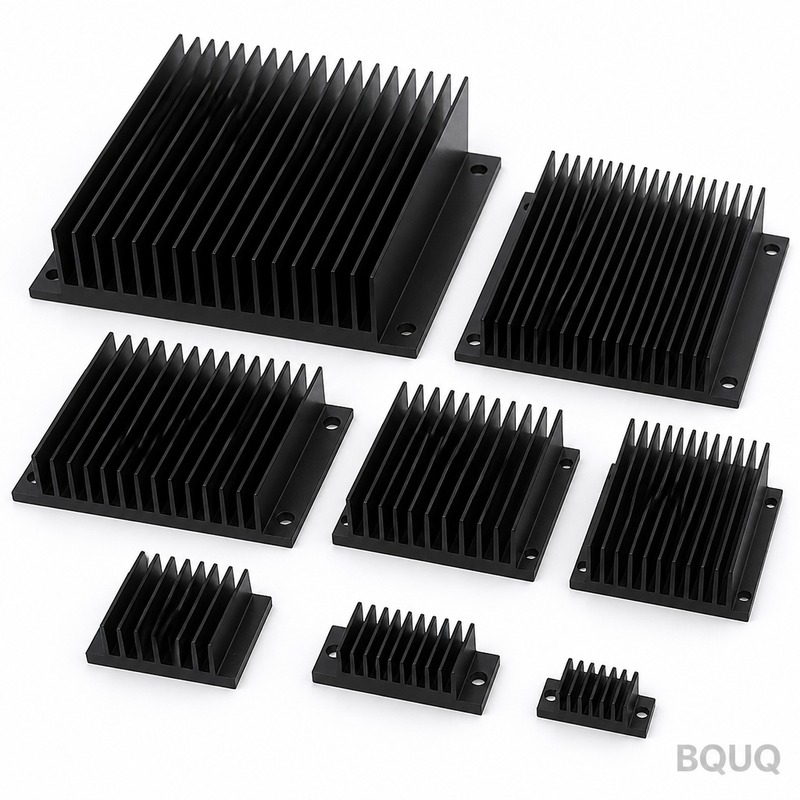
What Is a Natural Convection Heat Sink? Passive Cooling Design Guide
A natural convection heat sink is a passive thermal management component that dissipates heat solely through buoyancy-driven airflow, without fans or pumps. It relies on the principle that warm air rises, creating a continuous natural draft that carries heat away from the finned surface. This guide provides engineering specifications, performance data, and design rules for implementing natural convection cooling in applications where reliability, silence, and zero power consumption are critical.
How Does Natural Convection Cooling Actually Work?
Natural convection operates on the density gradient between heated and ambient air. As the heat sink base warms, it heats the adjacent air layer, reducing air density and causing it to rise. Cooler, denser air flows in from the bottom or sides to replace it, establishing a continuous circulation loop. The driving force is quantified by the Grashof number (Gr), which for typical electronics enclosures ranges from 10^4 to 10^7, indicating laminar to early-transition flow regimes. Unlike forced convection, which can achieve heat transfer coefficients of 50–250 W/m²K, natural convection coefficients are dramatically lower, typically 2–15 W/m²K. This means the heat sink surface area must be 5 to 20 times larger than a fan-cooled equivalent to dissipate the same thermal load.
What Are the Typical Performance Limits and Thermal Resistance Values?
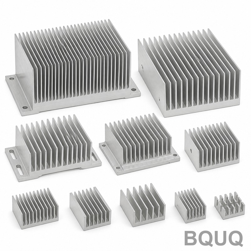
A well-designed natural convection heat sink can dissipate between 0.5 W and 50 W, depending on envelope size and orientation. For a standard extruded aluminum profile measuring 200 mm x 100 mm x 40 mm with a 10 mm fin pitch, the thermal resistance from junction-to-ambient typically ranges from 1.5 °C/W to 3.5 °C/W. The following table provides measured reference data for common configurations under natural convection at 25 °C ambient.
| Configuration | Fin Pitch (mm) | Fin Height (mm) | Base Thickness (mm) | Thermal Resistance (°C/W) | Max Power Dissipation (W) |
| Standard extruded profile, vertical fins | 8 | 25 | 8 | 2.8 | 18 |
| High-density extruded profile, vertical fins | 6 | 30 | 10 | 2.1 | 24 |
| Pin-fin heat sink, square pins, vertical orientation | 5 | 20 | 8 | 3.2 | 15 |
| Flat plate, no fins, vertical orientation | N/A | N/A | 10 | 6.5 | 7 |
| Skived fin heat sink, high aspect ratio | 4 | 40 | 12 | 1.8 | 28 |
These values assume a black anodized surface (emissivity 0.85) and a vertical mounting orientation. Horizontal orientation reduces performance by 20–30% due to disrupted airflow paths.
How Should You Calculate Fin Spacing and Height for Optimal Performance?
The optimal fin spacing for natural convection follows the Elenbaas correlation, where the ideal gap (b) is approximately 10.5 mm for a 25 mm tall fin at a 75 °C temperature difference. More precisely, the fin gap should be calculated so that the boundary layers from adjacent fins do not merge, which would choke the airflow. For aluminum fins with a temperature rise of 50 °C above ambient, the recommended fin spacing is 6–12 mm, with 8–10 mm being the sweet spot for most applications. Fin height should not exceed 10 times the fin gap; beyond this ratio, the upper portion of the fin becomes ineffective because the air has already reached near-ambient temperature. The fin thickness should be 1.5–3 mm for extruded aluminum, balancing material cost against conduction efficiency. A common mistake is using forced-convection fin spacing (2–4 mm) in a natural convection design, which reduces thermal performance by up to 40%.
Which Materials Offer the Best Thermal Conductivity for Passive Heat Sinks?
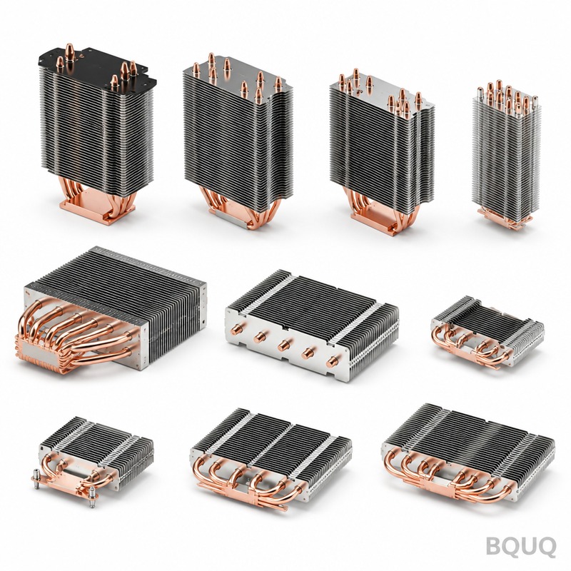
Aluminum 6063-T5 is the industry standard for natural convection heat sinks due to its excellent balance of thermal conductivity (201 W/m·K), extrudability, and cost at approximately USD 4–6 per kilogram. Copper provides 385 W/m·K, offering roughly 90% better conduction, but costs USD 12–15 per kilogram and is 3.3 times denser, which increases weight and cost significantly. For high-performance applications, copper heat sinks with aluminum fins are sometimes assembled using thermal epoxy or mechanical fastening, achieving 80–90% of solid copper performance at 60% of the weight. A cheaper alternative is ADC12 die-cast aluminum (96 W/m·K), suitable for complex geometries but requiring 20–30% more surface area to match extruded aluminum performance. Graphite-based materials (150–400 W/m·K in-plane) are emerging for flat-plate applications but are not cost-effective for three-dimensional finned structures. For most industrial electronics, 6063-T5 aluminum with a black anodized coating is the recommended choice, as anodizing increases emissivity from 0.04 to 0.85, improving radiative heat transfer by 15–25%.
How Does Surface Finish and Color Affect Radiative Heat Dissipation?
Radiative heat transfer accounts for 20–35% of total heat dissipation in natural convection, making surface treatment critical. A polished aluminum surface with emissivity of 0.04–0.09 radiates almost no heat, forcing convection to handle the entire load. Black anodized aluminum (emissivity 0.85–0.90) is the industry standard, increasing total heat dissipation by 25–35% compared to bare metal. Powder coating in matte black achieves similar emissivity (0.85–0.92) but adds 30–50 µm thickness, which can increase thermal resistance by 0.1–0.3 °C/W due to the coating's lower thermal conductivity. Clear anodizing offers minimal improvement (emissivity 0.15–0.30) and is not recommended for passive cooling. The surface finish also affects dust accumulation; textured surfaces trap particles, which can form an insulating layer of 0.1–0.5 mm and degrade performance by 10–15% over time. For outdoor or dusty environments, specify a smooth anodized finish with periodic cleaning intervals.
When Should You Choose a Skived Fin vs. Extruded vs. Bonded Fin Heat Sink?
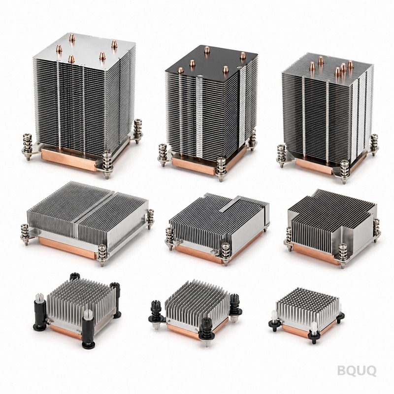
Extruded aluminum heat sinks are the most cost-effective option for natural convection, with tooling costs of USD 1,500–3,000 and minimum order quantities of 500 pieces. The maximum fin height-to-gap ratio is limited to about 10:1, which restricts fin density. Skived fin heat sinks use a cutting process that produces fins up to 40 mm high with gaps as small as 2.5 mm, offering up to 40% higher surface area per footprint than extruded designs; tooling costs are higher at USD 5,000–10,000, and piece prices run USD 8–20 for typical sizes. Bonded fin heat sinks, where individual fins are epoxied to a base plate, allow mixing materials (copper fins on aluminum base) and achieve fin densities up to 18 fins per inch, but the epoxy joint adds 0.5–1.0 °C/W thermal resistance. For natural convection specifically, the airflow is limited by buoyancy, so extremely dense fins do not help; a 6–12 mm gap is ideal. Choose extruded for volumes above 1,000 pieces and standard geometries, skived for high-performance requirements with fin heights above 30 mm, and bonded fin only when material mixing is essential.
What Are the Most Common Design Mistakes in Passive Cooling Systems?
The most frequent error is mounting the heat sink horizontally, which reduces natural convection performance by 30–50% because the heated air cannot rise freely away from the fins. A second critical mistake is placing the heat sink too close to an enclosure wall; a minimum clearance of 10–15 mm is required above the fin tips to allow air to escape and fresh air to enter. Third, designers often ignore the heat source spreading resistance; a 50 W IGBT (insulated-gate bipolar transistor) concentrated on a 20 mm x 20 mm footprint requires a base thickness of at least 8–12 mm to spread heat effectively across the fin array, otherwise the fins near the source run hot while outer fins remain cool. Fourth, using forced-convection fin spacing (2–4 mm) in a natural convection design reduces airflow and increases thermal resistance by 30–40%. Finally, neglecting the system-level airflow path—such as blocking intake vents or placing the heat sink downstream of a hot component—can raise the effective ambient temperature by 10–20 °C, halving the heat sink's performance margin.
How Can You Predict Natural Convection Performance Accurately?
Computational fluid dynamics (CFD) simulation is the most accurate method, with modern software achieving agreement within 5–10% of experimental measurements for natural convection. For preliminary estimates, the empirical correlation for vertical flat plates and finned arrays is Nu = 0.59 × (Gr × Pr)^0.25 for laminar flow, where Nu is the Nusselt number, Gr is the Grashof number, and Pr is the Prandtl number (0.71 for air). This correlation is valid for Rayleigh numbers (Ra = Gr × Pr) between 10^4 and 10^9. A simpler rule of thumb: for a vertically mounted aluminum heat sink, the thermal resistance in °C/W is approximately 250 divided by the total surface area in square centimeters, assuming a 50 °C temperature rise. For example, a heat sink with 500 cm² of total surface area would have an estimated resistance of 0.5 °C/W. Always apply a 10–20% derating factor for real-world conditions, including non-uniform airflow, enclosure restrictions, and elevated ambient temperatures above 50 °C.
Conclusion
Natural convection heat sinks are a reliable, zero-maintenance cooling solution for applications up to 50 W, provided the fin geometry, material, surface finish, and mounting orientation are correctly specified. The key engineering parameters are fin spacing of 6–12 mm, fin height-to-gap ratio under 10:1, black anodized aluminum with emissivity above 0.85, and vertical orientation with at least 10 mm clearance. When these rules are followed, a properly sized heat sink can achieve thermal resistances of 1.5–3.5 °C/W with predictable performance. For assistance with your passive cooling design, including thermal simulation, prototype development, and production runs, contact BQUQ’s engineering team for a 12-hour quote.
| Email: sc@bquq.com | WhatsApp: +86 13713157787 | www.bquq.com |


